Layer 3 -- My study notes and study technique

Layer 3 -- My study notes and study technique
![]() by daniel.larsson Fri May 15, 2015 12:36 pm
by daniel.larsson Fri May 15, 2015 12:36 pm
All-in-all though I would say that i'm roughly 50% through with my studies Before I will book the exam. So it's still a long journey! But I recently got asked how to prepare for the exam at Another Place so i will just add it in here as well for the information. So i quote:
Daniel Larsson wrote:I do get asked a lot of questions of how to prepare for exams or how to best learn a specific topic. I am slowly (too slowly) preparing myself for the RSv5 Lab exam and someone might find it interesting to know how to prepare for an exam like that.
So someone might find this interesting, but this is actually how I am currently studying for both CCDP and the CCIE RSv5 Lab. I find this technique to work very well for me and it makes sure I don't oversee any small details or any topic that I haven't heard of before.
This is a copy-and-paste from my CCIE Study-nots document, so mind the words used ;-).
While studying for the CCIE i tend to write a lot in my study-document to help with the learning process and to keep me motivated. But basically this is how I study and I quote my "little" document:
General study technique that eventually will make me a master of the CCIE RSv5 topics.
In the beginning i thought that i could apply the Layer 2 study technique to Layer 3 studies as well. It worked for some topics while others were impossible to find on the Cisco-website or in any configuration guide at all.
So i turned to using the same approach and use the configuration and technology explanations of the IOS 15.3T release for topics that could be found, and other theory resources for topics that was not on the cisco-website.
My general three basic steps are:
- -First, read through the configuration and technology explanations on the 15.3T IOS release if there is any for the specific topic in the blueprint. If there are none, go to other sources such as RFC's, Forums, CCIE blogs, Cisco-books and study the topic theory.
- -Secondly, watch INE CCIE videos about the topics to learn more in depth. I've noticed that their video-series does not follow their own re-ordered study-plan of the CCIE RSv5 blueprints. So I will watch the videos not in the order they come but rather in the order they align with the study-plan.
- -And lastly, lab it up using INE CCIE RSv5 topology and using their CCIE Workbook. Most topics are covered in their Workbook. However for some topics that I might not feel confident enough in i will create my own labs to verify the theory.
Repeat this for each and every topic that is in the CCIE RSv5 LAB blueprint. Layer 3 technologies consists of most part of the CCIE LAB so it's going to take a lot of time to prepare for this! Estimated the Layer 3 configuration is about 85% of the scope of the exam.
As a preparation for CCIE i have also noted my preparation time in this document listed by a per-technology basis. It will keep me reminded about how much time is invested in each topic in case i need to go back and study some more.
I will approach this lab by learning from scratch, meaning that I will read all design documents and all release notes about all the technologies that are listed in the CCIE blueprint just to be sure I at least have a decent chance of remembering reading about it in case i get tested on it during the lab. This also means that i may read a lot of basic-non CCIE level of theory to just see if I've missed anything.
For instance, i feel extremely confident in general routing such as (EIGRP, OSPF, BGP, RIP, Static) but I will still read through every "core" document by cisco on the technologies I can be tested on.
Note to self: Although my plan is to use the INE Study plan that Brian McGahan reordered for the CCIE RSv5 Lab blueprint i will have to make changes to the study plan and in which order to study just because their videos are not following their study-plan.
I will try to study according to the study plan and make it more aligned. For example, i will not do EIGRP before RIP as their Video series does. I will just do the theory in advance based on the labs in their workbook because their workbook is more aligned with their study plan.
As a final note i would just like to say that this technique may not work for all. In fact it may only work for me, but it works really well for me! I personally strongly recommend a simular approach of studying. Mainly because in this way you will learn what you DON'T already know and that will be your weakest area. So it will Always be good to get that on paper so you know what you need to study instead of studying what you already know!
The complete way of studying that I am preparing for the CCIE RSv5 Blueprint is how Brian McGahan reordered it. It makes perfect sense. Most of the topics i'll post below are my study notes and you'll see that they follow this list very much. I've made some Changes mainly in the Security part because I prefer to be through-and-done with a topic rather than go back at a later stage. I then cross every topic out of the list as I've studied them. That doesn't mean that I am ready with them, just that I have at least a foundational knowledge about them. It also helps with knowing how long away the Lab date is!
This is the list:
RSv5 Expanded Blueprint
Color explanation
Red = Not studied topics. (meaning I have not studies these topics at CCIE Level)
Blue = Studied topics that I consider myself Confident enough in.
Dark Red = Studied topics but I feel that I need to improve on Before lab.
Black = Topics initially in the Blueprint but was later removed.
3. IP Routing
..3.1. Protocol Independent IPv4 Routing
....3.1.2. IPv4 ARP
....3.1.3. Longest Match Routing
....3.1.4. Administrative Distance
....3.1.5. Static Routing
....3.1.6. Route Recursion
....3.1.7. Egress Interface vs. Next Hop Static Routing
....3.1.8. Default Routing
....3.1.9. CEF
....3.1.10. Floating Static Routes
....3.1.11. Backup Interface
....3.1.12. IP Service Level Agreement
....3.1.13. Enhanced Object Tracking
....3.1.14. Policy Routing
....3.1.15. Policy Routing and IP SLA
....3.1.16. Local Policy Routing
....3.1.17. GRE Tunnels
....3.1.18. IP in IP Tunnels
....3.1.19. Tunnels & Recursive Routing Errors
....3.1.20. On Demand Routing
....3.1.21. VRF Lite
....3.1.22. Bidirectional Forwarding Detection
....3.1.23. Performance Routing (PfR) *
..3.2. Protocol Independent IPv6 Routing
....3.2.1. IPv6 Link-Local Addressing
....3.2.2. IPv6 Unique Local Addressing
....3.2.3. IPv6 Global Aggregatable Addressing
....3.2.4. IPv6 EUI-64 Addressing
....3.2.5. IPv6 Auto-Configuration / SLAAC
....3.2.6. IPv6 Global Prefix
....3.2.7. IPv6 Redistribution
....3.2.8. IPv6 Filtering
....3.2.9. IPv6 NAT-PT
....3.2.10. IPv6 MP-BGP
....3.2.11. IPv6 Tunneling *
....3.2.12. Automatic 6to4 Tunneling*
....3.2.13. ISATAP Tunneling *
....3.3.1. Distance Vector vs. Link State vs. Path Vector routing protocols
....3.3.2. Passive Interfaces
....3.3.3. Routing Protocol Authentication
....3.3.4. Route Filtering
....3.3.5. Auto Summarization
....3.3.6. Manual Summarization
....3.3.7. Route Redistribution
......3.3.7.1. Prefix Filtering with Route Tagging
......3.3.7.2. Prefix Filtering with Manual Lists
......3.3.7.3. Prefix Filtering with Administrative Distance
......3.3.7.4. Administrative Distance Based Loops
......3.3.7.5. Metric Based Loops
..3.4. RIP
......3.4.1.1. Initialization
........3.4.1.1.1. Enabling RIPv2
........3.4.1.1.2. RIP Send and Receive Versions
........3.4.1.1.3. Split Horizon
........3.4.1.1.4. RIPv2 Unicast Updates
........3.4.1.1.5. RIPv2 Broadcast Updates
........3.4.1.1.6. RIPv2 Source Validation
......3.4.1.2. Path Selection
........3.4.1.2.1. Offset List
......3.4.1.3. Summarization
........3.4.1.3.1. Auto-Summary
........3.4.1.3.2. Manual Summarization
......3.4.1.4. Authentication
........3.4.1.4.1. Clear Text
........3.4.1.4.2. MD5
......3.4.1.5. Convergence Optimization & Scalability
........3.4.1.5.1. RIPv2 Convergence Timers
........3.4.1.5.2. RIPv2 Triggered Updates
......3.4.1.6. Filtering
........3.4.1.6.1. Filtering with Passive Interface
........3.4.1.6.2. Filtering with Prefix-Lists
........3.4.1.6.3. Filtering with Standard Access-Lists
........3.4.1.6.4. Filtering with Extended Access-Lists
........3.4.1.6.5. Filtering with Offset Lists
........3.4.1.6.6. Filtering with Administrative Distance
........3.4.1.6.7. Filtering with Per Neighbor AD
......3.4.1.7. Default Routing
........3.4.1.7.1. RIPv2 Default Routing
........3.4.1.7.2. RIPv2 Conditional Default Routing
........3.4.1.7.3. RIPv2 Reliable Conditional Default Routing
....3.4.2. RIPng *
......3.4.2.1. RIPng Overview *
3.5. EIGRP
3.5.1. Initialization
3.5.1.1. Network Statement
3.5.1.2. Multicast vs. Unicast Updates
3.5.1.3. EIGRP Named Mode
3.5.1.4. EIGRP Multi AF Mode
3.5.1.5. EIGRP Split Horizon
3.5.1.6. EIGRP Next-Hop Processing
3.5.2. Path Selection
3.5.2.1. Feasibility Condition
3.5.2.2. Modifying EIGRP Vector Attributes
3.5.2.3. Classic Metric
3.5.2.4. Wide Metric
3.5.2.5. Metric Weights
3.5.2.6. Equal Cost Load Balancing
3.5.2.7. Unequal Cost Load Balancing
3.5.2.8. EIGRP Add-Path
3.5.3. Summarization
3.5.3.1. Auto-Summary
3.5.3.2. Manual Summarization
3.5.3.3. Summarization with Default Routing
3.5.3.4. Summarization with Leak Map
3.5.3.5. Summary Metric
3.5.4. Authentication 3.5.4.1. MD5
3.5.4.2. HMAC SHA2-256bit
3.5.4.3. Automatic key rollover
3.5.5. Convergence Optimization & Scalability
3.5.5.1. EIGRP Convergence Timers
3.5.5.2. EIGRP Query Scoping with Summarization
3.5.5.3. EIGRP Query Scoping with Stub Routing
3.5.5.4. Stub Routing with Leak Map
3.5.5.5. Bandwidth Pacing
3.5.5.6. IP FRR
3.5.5.7. Graceful Restart & NSF
3.5.6. Filtering
3.5.6.1. Filtering with Passive Interface
3.5.6.2. Filtering with Prefix-Lists
3.5.6.3. Filtering with Standard Access-Lists
3.5.6.4. Filtering with Extended Access-Lists
3.5.6.5. Filtering with Offset Lists
3.5.6.6. Filtering with Administrative Distance
3.5.6.7. Filtering with Per Neighbor AD
3.5.6.8. Filtering with Route Maps
3.5.6.9. Per Neighbor Prefix Limit
3.5.6.10. Redistribution Prefix Limit
3.5.7. Miscellaneous EIGRP
3.5.7.1. EIGRP Default Network
3.5.7.2. EIGRP Default Metric
3.5.7.3. EIGRP Neighbor Logging
3.5.7.4. EIGRP Router-ID
3.5.7.5. EIGRP Maximum Hops
3.5.7.6. no next-hop-self no-ecmp-mode
3.5.7.7. EIGRP Route Tag Enhancements
3.5.8. EIGRPv6
3.5.8.1. Enabling EIGRPv6
3.5.8.2. EIGRPv6 Split Horizon
3.5.8.3. EIGRPv6 Next-Hop Processing
3.5.8.4. EIGRPv6 Authentication
3.5.8.5. EIGRPv6 Metric Manipulation
3.5.8.6. EIGRPv6 Default Routing
3.5.8.7. EIGRPv6 Summarization
3.5.8.8. EIGRPv6 Prefix Filtering
3.5.8.9. EIGRPv6 Stub Routing
3.5.8.10. EIGRPv6 Link Bandwidth
3.5.8.11. EIGRPv6 Timers
3.5.8.12. EIGRP IPv6 VRF Lite
3.5.8.13. EIGRP Over The Top
3.6. OSPF 3.6.1. Initialization 3.6.1.1. Network Statement
3.6.1.2. Interface Statement
3.6.2. Network Types 3.6.2.1. Broadcast
3.6.2.2. Non-Broadcast
3.6.2.3. OSPF DR/BDR Election Manipulation
3.6.2.4. Point-to-Point
3.6.2.5. Point-to-Multipoint
3.6.2.6. Point-to-Multipoint Non-Broadcast
3.6.2.7. Loopback
3.6.2.8. LSA Types
3.6.2.9. OSPF Next-Hop Processing
3.6.2.10. Unicast vs. Multicast Hellos
3.6.3. Path Selection 3.6.3.1. Auto-Cost
3.6.3.2. Cost
3.6.3.3. Bandwidth
3.6.3.4. Per-Neighbor Cost
3.6.3.5. Non-Backbone Transit Areas
3.6.3.6. Virtual-Links
3.6.4. Authentication 3.6.4.1. Area
3.6.4.2. Interface level
3.6.4.3. Clear Text
3.6.4.4. MD5
3.6.4.5. Null
3.6.4.6. MD5 with Multiple Keys
3.6.4.7. SHA1-196
3.6.4.8. Virtual link
3.6.5. Summarization 3.6.5.1. Internal Summarization
3.6.5.2. External Summarization
3.6.5.3. Path Selection with Summarization
3.6.5.4. Summarization and Discard Routes
3.6.6. Stub Areas 3.6.6.1. Stub Areas
3.6.6.2. Totally Stubby Areas
3.6.6.3. Not-So-Stubby Areas
3.6.6.4. Not-So-Stubby Areas and Default Routing
3.6.6.5. Not-So-Totally-Stubby Areas
3.6.6.6. Stub Areas with Multiple Exit Points
3.6.6.7. NSSA Type-7 to Type-5 Translator Election
3.6.6.8. NSSA Redistribution Filtering
3.6.7. Filtering 3.6.7.1. Filtering with Distribute-Lists
3.6.7.2. Filtering with Administrative Distance
3.6.7.3. Filtering with Route-Maps
3.6.7.4. Filtering with Summarization
3.6.7.5. LSA Type-3 Filtering
3.6.7.6. Forwarding Address Suppression
3.6.7.7. NSSA ABR External Prefix Filtering
3.6.7.8. Database Filtering
3.6.8. Default Routing 3.6.8.1. Default Routing
3.6.8.2. Conditional Default Routing
3.6.8.3. Reliable Conditional Default Routing
3.6.8.4. Default Cost
3.6.9. Convergence Optimization & Scalability 3.6.9.1. Interface Timers
3.6.9.2. Fast Hellos
3.6.9.3. LSA & SPF Throttling
3.6.9.4. LSA & SPF Pacing
3.6.9.5. Single Hop LFA / IP FRR
3.6.9.6. Multihop LFA
3.6.9.7. Stub Router Advertisement
3.6.9.8. Demand Circuit
3.6.9.9. Flooding Reduction
3.6.9.10. Transit Prefix Filtering
3.6.9.11. Resource Limiting
3.6.9.12. Graceful Restart & NSF
3.6.9.13. Incremental SPF
3.6.10. Miscellaneous OSPF Features
3.6.11. OSPFv3 3.6.11.1. LSA Types
3.6.11.2. OSPFv3
3.6.11.3. OSPFv3 Network Types
3.6.11.4. OSPFv3 Prefix Suppression
3.6.11.5. OSPFv3 Virtual Links
3.6.11.6. OSPFv3 Summarization
3.6.11.7. OSPFv3 IPsec Authentication
3.6.11.8. OSPFv3 Multi AF Mode
3.6.11.9. TTL Security
3.7. BGP 3.7.1. Establishing Peerings 3.7.1.1. iBGP Peerings
3.7.1.2. EBGP Peerings
3.7.1.3. Update Source Modification
3.7.1.4. Multihop EBGP Peerings
3.7.1.5. Neighbor Disable-Connected-Check
3.7.1.6. Authentication
3.7.1.7. TTL Security
3.7.1.8. BGP Peer Groups
3.7.1.9. 4 Byte ASNs
3.7.1.10. Active vs. Passive Peers
3.7.1.11. Path MTU Discovery
3.7.1.12. Multi Session TCP Transport per AF
3.7.1.13. Dynamic BGP Peering
3.7.2. iBGP Scaling 3.7.2.1. Route Reflectors
3.7.2.2. Route Reflector Clusters
3.7.2.3. Confederations
3.7.3. BGP Next Hop Processing 3.7.3.1. Next-Hop-Self
3.7.3.2. Manual Next-Hop Modification
3.7.3.3. Third Party Next Hop
3.7.3.4. Next Hop Tracking
3.7.3.5. Conditional Next Hop Tracking
3.7.3.6. BGP Next-Hop Trigger Delay
3.7.4. BGP NLRI Origination 3.7.4.1. Network Statement
3.7.4.2. Redistribution
3.7.4.3. BGP Redistribute Internal
3.7.4.4. Conditional Advertisement
3.7.4.5. Conditional Route Injection
3.7.5. BGP Bestpath Selection 3.7.5.1. Weight
3.7.5.2. Local Preference
3.7.5.3. AS-Path Prepending
3.7.5.4. Origin
3.7.5.5. MED
3.7.5.6. Always Compare MED
3.7.5.7. Deterministic MED
3.7.5.8. AS-Path Ignore
3.7.5.9. Router-IDs
3.7.5.10. DMZ Link Bandwidth
3.7.5.11. Maximum AS Limit
3.7.5.12. Multipath
3.7.6. BGP Aggregation 3.7.6.1. BGP Auto-Summary
3.7.6.2. Aggregation
3.7.6.3. Summary Only
3.7.6.4. Suppress Map
3.7.6.5. Unsuppress Map
3.7.6.6. AS-Set
3.7.6.7. Attribute-Map
3.7.6.8. Advertise Map
3.7.7. BGP Communities 3.7.7.1. Standard
3.7.7.2. Extended
3.7.7.3. No-Advertise
3.7.7.4. No-Export
3.7.7.5. Local-AS
3.7.7.6. Deleting
3.7.8. Filtering 3.7.8.1. Prefix-Lists
3.7.8.2. Standard Access-Lists Task
3.7.8.3. Extended Access-Lists
3.7.8.4. Maximum Prefix
3.7.8.5. BGP Regular Expressions
3.7.8.6. Outbound Route Filtering (ORF)
3.7.8.7. Soft Reconfiguration Inbound
3.7.9. AS-Path Manipulation 3.7.9.1. Local AS
3.7.9.2. Local AS Replace-AS/Dual-AS
3.7.9.3. Remove Private AS
3.7.9.4. Allow AS In
3.7.9.5. AS Override
3.7.10. BGP Convergence Optimization 3.7.10.1. BGP Timers Tuning
3.7.10.2. BGP Fast Fallover
3.7.10.3. BGP Prefix Independent Convergence (PIC)
3.7.10.4. BGP Dampening
3.7.10.5. BGP Dampening with Route-Map
3.7.10.6. BGP Add Path
3.7.11. BGP Default Routing
3.7.12. IPv6 BGP
3.7.13. Misc BGP 3.7.13.1. iBGP Synchronization
3.7.13.2. BGP over GRE
3.7.13.3. BGP Backdoor
3.8. Route Redistribution 3.8.1. Metric Based Loops
3.8.2. Administrative Distance Based Loops
3.8.3. Route Tag Filtering
3.8.4. IP Route Profile
3.8.5. Debug IP Routing
3.9. Miscellaneous Routing Features
3.10. IS-IS *
4. VPN
4.1. MPLS 4.1.1. VRF Lite
4.1.2. MPLS LDP
4.1.3. MPLS Ping
4.1.4. MPLS Traceroute
4.1.5. MPLS Label Filtering
4.1.6. MP-BGP VPNv4
4.1.7. MP-BGP Prefix Filtering
4.1.8. PE-CE Routing with RIP
4.1.9. PE-CE Routing with OSPF
4.1.10. OSPF Sham-Link
4.1.11. PE-CE Routing with EIGRP
4.1.12. EIGRP Site-of-Origin
4.1.13. PE-CE Routing with BGP
4.1.14. BGP SoO Attribute
4.1.15. Internet Access
4.1.16. Route Leaking
4.1.17. MPLS VPN Performance Tuning
4.1.18. AToM *
4.1.19. L2TPV3 *
4.1.20. VPLS *
4.2. IPsec LAN-to-LAN 4.2.1. ISAKMP Policies
4.2.2. PSK Authentication
4.2.3. Static Crypto Maps
4.2.4. IPsec over GRE
4.2.5. Static VTI
4.2.6. GETVPN *
4.3. DMVPN 4.3.1. Single Hub
4.3.2. NHRP
4.3.3. DMVPN Phase 1, 2, & 3
4.3.4. QoS Profiles
4.3.5. QoS Pre-Classify
5. Multicast
5.1. Layer 2 Multicast 5.1.1. IGMPv1, IGMPv2, IGMPv3
5.1.2. IGMP Snooping
5.1.3. IGMP Querier Election
5.1.4. IGMP Filtering
5.1.5. IGMP Proxy
5.1.6. IGMP Timers
5.1.7. Multicast VLAN Registration
5.1.8. IGMP Profiles
5.2. IPv4 Multicast Routing 5.2.1. PIM Dense Mode
5.2.2. PIM Sparse Mode
5.2.3. PIM Sparse Dense Mode
5.2.4. Static RP
5.2.5. Auto-RP 5.2.5.1. Auto-RP
5.2.5.2. Sparse Dense Mode
5.2.5.3. Auto-RP Listener
5.2.5.4. Multiple Candidate RPs
5.2.5.5. Filtering Candidate RPs
5.2.5.6. RP & MA placement problems
5.2.6. Bootstrap Router 5.2.6.1. BSR
5.2.6.2. Multiple RP Candidates
5.2.6.3. Multiple BSR Candidates
5.2.7. Source Specific Multicast
5.2.8. Bidirectional PIM
5.2.9. Group to RP Mapping
5.2.10. Anycast RP
5.2.11. MSDP
5.2.12. MSDP SA Filtering
5.2.13. Multicast TTL Scoping
5.2.14. Auto-RP & BSR Boundary Filtering
5.2.15. PIM Accept Register Filtering
5.2.16. PIM Accept RP Filtering
5.2.17. RPF Failure
5.2.18. Registration Failure
5.2.19. PIM DR Election
5.2.20. PIM DF Election
5.2.21. PIM Assert
5.2.22. Static Multicast Routes
5.2.23. Multicast BGP
5.2.24. PIM NBMA Mode
5.2.25. Multicast over GRE
5.2.26. Stub Multicast Routing
5.2.27. Multicast Helper Map
5.2.28. Multicast Rate Limiting
5.2.29. Multicast BGP
5.3. IPv6 Multicast Routing * 5.3.1. IPv6 PIM and MLD *
5.3.2. IPv6 PIM BSR *
5.3.3. IPv6 Embedded RP *
5.3.4. IPv6 SSM *
6. QoS
6.1. Hold-Queue and Tx-Ring
6.2. Weighted Fair Queuing (WFQ)
6.3. Selective Packet Discard
6.4. Payload Compression on Serial Links
6.5. Generic TCP/UDP Header Compression
6.6. MLP Link Fragmentation and Interleaving
6.7. MQC Classification and Marking
6.8. MQC Bandwidth Reservations and CBWFQ
6.9. MQC Bandwidth Percent
6.10. MQC LLQ and Remaining Bandwidth Reservations
6.11. MQC WRED
6.12. MQC Dynamic Flows and WRED
6.13. MQC WRED with ECN
6.14. MQC Class-Based Generic Traffic Shaping
6.15. MQC Class-Based GTS and CBWFQ
6.16. MQC Single-Rate Three-Color Policer
6.17. MQC Hierarchical Policers
6.18. MQC Two-Rate Three-Color Policer
6.19. MQC Peak Shaping
6.20. MQC Percent-Based Policing
6.21. MQC Header Compression
6.22. Voice Adaptive Traffic Shaping
6.23. Voice Adaptive Fragmentation
6.24. Advanced HTTP Classification with NBAR
6.22. Layer 2 QoS *
7. Security
7.1. Layer 2 Security 7.1.1. Port Protection
7.1.2. Private VLANs
7.1.3. Port Based ACLs
7.1.4. VLAN ACLs for IP Traffic
7.1.5. VLAN ACLs for Non-IP Traffic
7.1.6. Storm Control
7.1.7. Port Security
7.1.8. HSRP and Port-Security
7.1.9. ErrDisable Recovery
7.1.10. DHCP Snooping
7.1.11. DHCP Snooping and the Information Option
7.1.12. Dynamic ARP Inspection
7.1.13. IP Source Guard
7.1.14. 802.1x *
7.2. Management Plane Security 7.2.1. AAA Authentication Lists
7.2.2. AAA Exec Authorization
7.2.3. AAA Local Command Authorization
7.2.4. Controlling Terminal Line Access
7.2.5. IOS Login Enhancements
7.2.6. IOS Resilient Configuration
7.2.7. Role-Based CLI
7.2.8. AAA with TACACS+ and RADIUS *
7.3. Control Plane Security 7.3.1. Controlling the ICMP Messages Rate
7.3.2. Control Plane Policing
7.3.3. Control Plane Protection (CPPr)
7.3.4. Control Plane Host
7.4. Data Plane Security 7.4.1. Traffic Filtering Using Standard Access-Lists
7.4.2. Traffic Filtering Using Extended Access-Lists
7.4.3. Traffic Filtering Using Reflexive Access-Lists
7.4.4. IPv6 Traffic Filter
7.4.5. Filtering Fragmented Packets
7.4.6. Filtering Packets with Dynamic Access-Lists
7.4.7. Filtering Traffic with Time-Based Access Lists
7.4.8. Traffic Filtering with Policy-Based Routing
7.4.9. Preventing Packet Spoofing with uRPF
7.4.10. Using NBAR for Content-Based Filtering
7.4.11. TCP Intercept
7.4.12. TCP Intercept Watch Mode
7.4.13. Packet Logging with Access-Lists
7.4.14. IP Source Tracker
7.4.15. Router IP Traffic Export (RITE)
7.4.16. IOS ACL Selective IP Option Drop
7.4.17. Flexible Packet Matching
7.4.18. IPv6 First Hop Security 7.4.18.1. RA guard
7.4.18.2. DHCP guard
7.4.18.3. Binding table
7.4.18.4. Device tracking
7.4.18.5. ND inspection/snooping
7.4.18.6. Source guard
7.4.18.7. PACL
8. System Management
8.1. Device Management 8.1.1. Console
8.1.2. Telnet 8.1.2.1. Telnet Service Options
8.1.3. SSH
8.1.4. Terminal Line Settings
8.1.5. HTTP Server and Client
8.1.6. FTP Server and Client
8.1.7. TFTP Server and Client
8.1.8. SNMP 8.1.8.1. SNMPv2 Server
8.1.8.2. SNMPv2c Access Control
8.1.8.3. SNMP Traps and Informs
8.1.8.4. CPU and Memory Thresholds
8.1.8.5. SNMPv3
8.1.8.6. SNMP MAC Address Notifications
8.1.8.7. SNMP Notifications of Syslog Messages
8.2. Logging 8.2.1. System Message Logging
8.2.2. Syslog Logging
8.2.3. Logging Counting and Timestamps
8.2.4. Logging to Flash Memory
8.2.5. Configuration Change Notification and Logging
8.2.6. Configuration Archive and Rollback
8.2.7. Logging with Access-Lists
8.3. NTP 8.3.1. NTP
8.3.2. NTP Authentication
8.3.3. NTP Access Control
8.3.4. NTP Version 3 & 4
8.4. EEM 8.4.1. KRON Command Schedule
8.4.2. EEM Scripting: Interface Events
8.4.3. EEM Scripting: Syslog Events
8.4.4. EEM Scripting: CLI Events
8.4.5. EEM Scripting: Periodic Scheduling
8.4.6. EEM Scripting: Advanced Features
8.4.7. EEM Applets
8.5. Miscellaneous System Management 8.5.1. Auto-Install over LAN Interfaces using DHCP
8.5.2. Auto-Install over LAN Interfaces Using RARP
8.5.3. IOS Menus
8.5.4. IOS Banners
8.5.5. Exec Aliases
8.5.6. TCP Keepalives
8.5.7. Generating Exception Core Dumps
8.5.8. Conditional Debugging
8.5.9. Tuning Packet Buffers
8.5.10. CDP
8.5.11. Remote Shell
9. Network Services
9.1. Object Tracking 9.1.1. IP SLA
9.1.2. Enhanced Object Tracking
9.1.3. Tracking Lists
9.2. First Hop Redundancy Protocols 9.2.1. HSRP
9.2.2. VRRP
9.2.3. GLBP
9.2.4. Router Redundancy and Object Tracking
9.2.5. IPv6 RS & RA Redundancy
9.3. DHCP 9.3.1. DHCP Server
9.3.2. DHCP Client
9.3.3. DHCP Relay
9.3.4. DHCP Host Pools
9.3.5. DHCP On-Demand Pool
9.3.6. DHCP Proxy
9.3.7. DHCP Information Option
9.3.8. DHCP Authorized ARP
9.3.9. SLAAC/DHCPv6 interaction
9.3.10. Stateful & Stateless DHCPv6
9.3.11. DHCPv6 prefix delegation
9.4. DNS 9.4.1. IOS Authoritative DNS Server
9.4.2. IOS Caching DNS Server
9.4.3. IOS DNS Spoofing
9.5. NAT 9.5.1. Basic NAT
9.5.2. NAT Overload
9.5.3. NAT with Route Maps
9.5.4. Static NAT
9.5.5. Static PAT
9.5.6. Static NAT and IP Aliasing
9.5.7. Static Policy NAT
9.5.8. NAT with Overlapping Subnets
9.5.9. TCP Load Distribution with NAT
9.5.10. Stateful NAT with HSRP
9.5.11. Stateful NAT with Primary/Backup
9.5.12. NAT Virtual Interface
9.5.13. NAT Default Interface
9.5.14. Reversible NAT
9.5.15. Static Extendable NAT
9.5.16. NAT ALG
9.6. Traffic Accounting 9.6.1. IP Precedence Accounting
9.6.2. IP Output Packet Accounting
9.6.3. IP Access Violation Accounting
9.6.4. MAC Address Accounting
9.7. NetFlow 9.7.1. Netflow v5 & v9
9.7.2. Netflow Ingress and Egress
9.7.3. Netflow Top Talkers
9.7.4. Netflow Aggregation Cache
9.7.5. Netflow Random Sampling
9.7.6. Netflow Input Filters
9.7.7. Netflow Export
9.8. Miscellaneous Network Services 9.8.1. Proxy ARP
9.8.2. IRDP
9.8.3. Router ICMP Settings 9.8.3.1. TCP Optimization
9.8.4. IOS Small Services and Finger
9.8.5. Directed Broadcasts and UDP Forwarding
9.8.6. NBAR Protocol Discovery
9.8.7. IP Event Dampening
9.8.8. Conditional Debugging
9.8.9. Embedded Packet Capture
9.8.10. Interpreting Packet Captures
Last edited by daniel.larsson on Mon Jun 22, 2015 12:48 am; edited 15 times in total

daniel.larsson- Admin
- Posts : 47
Join date : 2015-04-30
Age : 41
Location : Boras, Sweden -

Layer 3 - How to approach the Studyplan, The INE CCIE RSv5 Workbook and their ATC (Advanced Technology Class)
![]() by daniel.larsson Fri May 15, 2015 4:52 pm
by daniel.larsson Fri May 15, 2015 4:52 pm
Technology: Protocol Independent IPv4 Routing
Since this is my first study notes on the Layer 3 part I need to remember how to approach all the topics since it's a very big scope. Roughly estimated it is 85% of the lab that's going to be IP-based.
My study technique above was written down to help me Learning in a structured way and for easy looking back. As I understood quickly the same approach for Layer 3 as I did with Layer 2 is not possible because of many reasons.
So what I came up with that worked the best for me was a way of researching in advance which topics i should study Before watching the videos and looking for information to match the study-plan. It took me a lot of trial and error Before figuring out a good way to achieve a path that was aligned with the study-plan and the CCIE RSv5 Blueprint topics released by Cisco. Now I decided a long time ago to go with INE and their way of studying because I feel that they have developed some very good books and videos, and most importantly. I find their instructors to be very detailed and interesting and they cover the topics from a CCIE perspective. I liked their way best of all other vendors i tried!
There was also the fact that i've met many CCIE's that's also been using INE and they recommended their way!
Now my problem with working with INE is that:
-They have a Workbook.
-They have an Advanced Technology Class video series.
-They have their topology and their rack rentals.
-And they have their study-plan developed by Brian McGahan.
The problem is, their workbook and their ATC (Advanced Technology Class) videos are not aligned with their study-plan!
So in the beginning i was quite....disturbed by the fact that their study-plan is not aligned with either the workbook or their ATC. It was difficult to really have a good plan that followed theory, instructors and practice labs.
After a lot of trying different methods I came to the conclusion that this was what I had to do go keep Everything aligned for a better learning strategy:
-Step 1. Look at the INE RSv5 Workbook and see which labs come next.
-Step 2. Look at the study plan and try to match the topic to the next labs in the Workbook, for example IP-Routing, Protocol Independent IPv4 Routing.
-Step 3. Don't Watch, but look at the various powerpoint-presentation/slides to learn which topics are covered in the ATC-video. Write these down!
-Step 4. Research about where you can study the different topics covered in the ATC-video, and write them down. Be sure to cover them all!
-Step 5. Study the theory about these topics.
-Step 6. Watch the same ATC-video completely.
-Step 7. Do the INE RSv5 Workbook labs that covers all the topics discussed in the ATC-video.
To better understand why I Think this is needed, let's give an example:
1. I looked at the INE RSv5 Workbook and came to the conslusion that after the Layer 2 labs the next labs that followed were these:
- Routing to Multipoint Broadcast Interfaces
- Routing to NBMA Interfaces
- Longest Match Routing
- Floating Static Routes
...and so on
(i usually check a few labs a head to try and group simular topics in a single study-session)
2. I then looked at the study plan and see that these labs at least covers these topics:
..3.1. Protocol Independent IPv4 Routing
....3.1.1. IPv4 Addressing
....3.1.2. IPv4 ARP
Obviously we need to understand IPv4 addresses and how to configure them to set up any kind of routing in the first place!
Also since Routing requires some sort of address-resolution to work, we also need to completely understand ARP to even send a packet towards an interface!
(ARP is arguably a layer 2 topic, it's definately a layer 2 protocol but it makes the most sense to learn ARP while studying IP!)
....3.1.3. Longest Match Routing
....3.1.5. Static Routing
We need to understand how the router matches a packet in the routing-table before forwarding it.
And also the very basic of routing is to configure a static-route. Since the lab said "routing to" it's logical to assume that knowledge of static-routing is needed.
....3.1.6. Route Recursion
....3.1.8. Default Routing
....3.1.10. Floating Static Routes
....3.1.4. Administrative Distance
....3.1.7. Egress Interface vs. Next Hop Static Routing
....3.1.9. CEF
Here's where it gets a little bit tricker. Since this is CCIE Study notes I will assume that at least CCNP-knowledge is required as a foundation before starting.
Route recursion is needed to understand how a route is ultimately chosen and resolves an exit-interface.
Default routing says itself, if there are no longest-match specific route in the table we need to know how to tell the router what to do with packets that don't match a route.
Floating Static Route - simple enough since there was a lab that said so!
Administrative Distance - because it has to do with how the router chooses which route to install in the routing-table, and the labs were about routing.
Egress Interface s Next-Hop Static Routing - More difficult to put here, but since the labs said "Multipoint Broadcast Interfaces" and "Routing to NBMA Interfaces" i know this fits here because of how ARP works.
3. I just look at the ATC-video to see which topics is covered and break out the details. In this case:
IP Routing Process Overview
..Routing
..Switching
..Encapsulation
Routing to a Next-Hop
..Recurse to the interface
..If multipoint, resolve next-hop
Routing to a Multipoint Interface
..Recursion not required
..Resolve address for final destination
Routing to a Point-to-Point interface
Default Routing
..To a next-hop
..To a Multipoint interface
..To a point-to-point interface
Note: At this stage it's possible that you may have to add topics to study for step 2.
4. I try to find the best places available to study all of these topics Before i'm ready to Watch the video.
Note: In this perticular case it's some "basic" topics. Too basic to be well documented on Cisco's webpage.
5. I then study those tpoics and write down what i learn and how much time it took me.
6. I then Watch the ATC-video too get in-depth knowledge from an instructor and hopefully learn something that i missed along the way!
7. Finally I do the labs with having a good strong Foundation knowledge about the topics.
Note: Some of the labs including the topics can be very basic, some of them extremelyl advanced. Here you would have to break down the topic and create your own labs and mess with it. Break it, solve it, learn it. For the most part INE does a very good job by slowly adding the difficulties, but some topics are just very little labs on. So be honest with yourself when doing the labs!
This may seem very time consuming at first, but here's why i recommend to do it this way:
1. For a starter you get a study-plan and a topic-by-topic study that is 100% aligned with the INE Workbook and their ATC-videos.
(i don't know about you, but I think it's much easier to prepare this way instead of jumping around topics)
2. You will also know exactly which topics you have studied for your study-plan, whether you are using your own or the Cisco RSv5 blueprint topics.
(Among all the things i've done during my studies so far, this is probably the most important one so I know what i've left!)
3. You will learn how to navigate the cisco webpage. I can not even tell you how extremely important that is since it will be available on the lab! You will be frustrated at first, but you will know where to find the topics IF you require it during the lab!
daniel.larsson- Admin
- Posts : 47
Join date : 2015-04-30
Age : 41
Location : Boras, Sweden -
Layer 3 - Protocol Independent IPv4 Routing PART 1
![]() by daniel.larsson Thu May 21, 2015 12:08 pm
by daniel.larsson Thu May 21, 2015 12:08 pm
Technology:
- IPv4 Addressing
- ARP
- Basic Routing Process Overview
- Longest Match Routing
- Administrative Distance
- Static Routing & Egress Interface vs Next Hop Static Routing
- Route Recursion
- Default Routing
- floating Static Routes
- CEF
Note before reading:
These study notes for Layer 3 technologies are rather long but that's mainly becuase there is a lot to read before doing labs when you reach Layer 3. Even the very basic parts requires you to thoroughly read through the topics. This specific part of the CCIE RSv5 blueprints covers all the basics, like really basic stuff, so the book required here is at about CCNA-level. I split the Protocol Independent Routing up in two parts, PART 1 i will cover the very basics of routing. Part 2 I will step it up a bit and go for the new/unknown topics.
Protocol Independent IPv4 Routing - PART 1
(Basic Routing Process Overview, IPv4 Addressing, ARP, Longest Match Routing, Administratie Distance, Static Routing, Route Recursion)
Note: A very "broad" topic that involves the very basic of routing from the scratch. Multiple sources are required to cover these topics, some of them from cisco and some of them from books. There's no red line to follow in this part, it's extremely messy!
I will start with IP-addresses and ARP, then move forward to how the routing process work and end this part with how the router selects how to make a decision about a packet.
The main book I found to be most usefull here is the old CCNA Exploration - Network Fundamentals and Routing Protocols and Concepts. Yes this is still very basic topics and there's no other book that explains it better that i've read!
Looking through the topics for this part it's clear to me that they are a foundation topics with the main goal to re-learn some of the basics and be familiar with basic routing before moving on. That's why i'll keep the sources at CCNA/CCNP level and combine it with the IOS configuration guide.
IPv4 Addressing
- Read through a chapter of the "CCDA Official Certification Book" that covers IPv4 in depth. Of all the sources i looked through I found this to be a good match to cover the basics.
Book: CCDA Official Certification Guide, Chapter 8.
Chapter 8 is named: Internet Protocol Version 4. - Read through Configuration and technology explanations of IPv4 Addressing for the 15.0 IOS release.
http://www.cisco.com/c/en/us/td/docs/ios-xml/ios/ipaddr_ipv4/configuration/15-mt/ipv4-15-mt-book/config-ipv4-addr.html
Learned:
-The Total Length field in the IPv4 header is compared against the outgoing interface MTU-value to determine if the packet needs to be fragmented or not. In other words, if the Total Length value is greater than the outgoing interface MTU-value the packet will be defragmented.
-Defragmentation is permanent all the way to the destination IP-host. The only check that is made is whether or not the Total Length Field is greater or smaller than the outgoing interface MTU-value. This means that a packet can be defragmented multiple times along the path to the final IP-host.
-The ToS field in the IPv4 header has gone through multiple changes over the years:
1981 (RFC 791) - A.k.a the original IP Precedence bits
1992 (RFC 1349) - A.k.a the extended IP Precedence bits
1998 (RFC 2474) - A.k.a the Differentiated Services / Differentiated Services Codepoint bits
2001 (RFC 3168) - A.k.a the DS / DSCP bits with an added Explicit Congestion Notification field
This is what we would call QoS or Quality of service. It's outside the scope of this topic but I'll get back to this part when im studying the QoS parts. What I wrote this down for is because it's good to learn and remember that they are all different names for the same thing, classify traffic so you can prioritize traffic classes independently. Starting with just a few bits (7 traffic classes) in 1981 and up to 6 bits (64 different traffic types) in the latest RFC.
-As could be expected a router requires each individual interface to be configured to belong in a different subnet. However it's possible, by manually adjusting router settings, to allow the configuration to accept commands that would let a router have multiple interfaces in say the 192.168.0.0/24 network. (ip routing disabled, ip addresses can be configured still)
What happens then is that the packet would be un-routable if both interfaces are not connected to the same network-segment. Because the router would not know out which interface to send a packet if the hosts are in different segments but in the same network.
Thus the IOS on a Cisco-router prevents such configuration mistakes from happening. But as meantioned, when disabling ip-routing on the router it's possible to configure ip-adresses still and in that case the IOS does not perform this check.
-It's possible to configure multiple ip-addresses on the same interface for migration purposes. Doing this will make that interface belong to multiple networks and as such it will receive unicast, broadcast and multicast packets destined for both networks.
-When doing subneting subnet 0 is reserved in some IOS-releases. If it's required to use the "subnet 0" subnet then the command "ip subnet-zero" is required.
-One very usefull command that i was unaware of was that it's possible to configure the way the IOS presents the subnet-mask format in. The default mode is the "dotted decimal form", for example 255.255.255.0 .
The command: term ip netmask-format bitcount ... would present it in a CIDR-notation, such as /24 instead!
Note: This command is also possible to set individually for each line (for example line con 0, line vty 4 15 etc)
-It's possible to configure an interface to use the ip address of another interface. This is called the "ip unnumbered" feature and is used to preserv ip-addresses.
This command is only usable ont Point-to-Point WAN-links (non multiaccess interfaces):
configure terminal
int loopback 0
ip address 192.168.0.0 255.255.255.0
int fa0/1
ip unnumbered loopback 0
end
(actually in a real world scenario it's more common to use the ip unnumbered command on the serial interfaces or whichever interface your point-to-point links have)
This will make Fa0/1 use the ip-address configured on loopback 0 interface.
-With newer IOS-releases it's possible to use the Host-address and the Broadcast address for non multiaccess Point-to-Point links. In other words it's possible to use a /31 mask for Point-to-Point links now instead of the previous most commonly used /30 mask.
Time required: 1½ hour.
ARP - Read through a chapter of the "CCNA Exploration - Network Fundamentals Book" that covers the basics of ARP. There are many sources for in depth-explanation of ARP but I believe that if I just have a good solid foundational understanding of ARP it will be enough. I will go more in depth when I come to the Security topics.
Book: CCNA Exploration - Network Fundamentals, Chapter 9.
Chapter 9 is named: Ethernet.
More specifically part 9.7 is called "Address Resolution Protocol" and that was exactly what I was looking for! - Read through Configuration and technology explanations of ARP for the 15.0 IOS release.
http://www.cisco.com/c/en/us/td/docs/ios-xml/ios/ipaddr_arp/configuration/15-mt/arp-15-mt-book/arp-config-arp.html - Read through Configuration and Technology explanations of Monitoring and Maintaining ARP Information for the 15.0 IOS release.
http://www.cisco.com/c/en/us/td/docs/ios-xml/ios/ipaddr_arp/configuration/15-mt/arp-15-mt-book/arp-monitor-arp.html
Learned:
-The ARP table/cache is stored in RAM unless a manually configured entry is added. The static entry never ages out and is stored in the running-config.
-The ARP table/cache is maintainted in a simular way as the switches maintain their MAC-tables. ARP-to-IP bindings (a mapping) can be learned in a received frame by looking at the source-ip, or when sending a frame by looking at the destination-ip, or by broadcasting for a destination IP and get a reply back.
-In Legacy network it's possible to be having hosts running older verions of ARP that can't derive if the destination IP-address it's trying to reach is inside the local subnet or at a remote-network.
This means that instead of senind an ARP-message with a destination of the configured Default-Gateway the ARP-broadcast will go towards the end Destination IP-address. In this scenario any packet will be droped unless some other feature is configured to respond to ARP-messages that's not intended for the local interface.
Proxy-ARP is such a feature and was designed to overcome this problem. Also with Proxy-ARP configured it's possible to have hosts on your network configured without a default-gateway.
-The default ARP-cache time limit is 4 hours on Cisco routers.
-Cisco referes to ARP as a Layer 3 protocol, which i think is outrageous since it's obviously not using IP-addresses for anything. I do need to remember that Cisco see this as a L3 protocol, and not a L2 protocol that it actually is.
The ARP-process is a sub-process of the Layer 2 process running. ARP carries Layer 3 information but all the communication is done over L2 so it can possibly never be a Layer 3 protocol.
-There are a couple of alterations of ARP mainly used in legacy networks. Examples are:
IARP, RARP, SLARP. IARP is used with ATM-connections, RARP is used when the MAC-address it known and the host requires an ip-address from a RARP server. RARP then sends a request to the RARP-server. The RARP server will respond with the correct IP-address for the RARP-host.
-Proxy ARP is enabled by default and can be globally disabled with the command "ip arp proxy disable" or in interface configuration mode with the command "no ip proxy-arp"
-ARP High Availibility (ARP HA) is the terminology Cisco uses for routers with multiple Route Processors.
-Cisco does not plan on implement any ARP-security features for routers since their recommendation is to stop Man-in-the-Middle attacks (ARP attacks) in the switching path leading towards the routers!
-Since IOS 12.4 Cisco lets you view ARP-entries and select exactly how you want to view them based on Interface, VRF-Table, Host or Network or per Router Interface.
-Two commands were introduced to help with ARP information. show arp & show ip arp.
The difference between them is that show arp display all Address Resolution Protocols where as show ip arp only displays information about the Internet Address Resolution Protocol.
-With newest IOS it's possible to debug ARP-events based on an Access-List to filter in on only specific ARP-information.
-By default the router is configured to learn infinite amount of ARP-entries. Eacy entry consumes available memory since the ARP-cache/table is stored in the RAM. When the RAM is full no more entries can be learned and no more RAM-resources are available for other processes required on the router.
The command " ip arp entry learn max-limit " limits the amount of RAM that can be used by ARP-entries.
-debug list 1000 , this command lets you configure an extended ACL and capture traffic based on a specific source MAC-address and a specific Destination MAC-address and debug only entries that is captured by the ACL.
Time required: 1½ hours
Basic Routing Process Overview (Routing, Switching, Encapsulation) - Read through a very old chapter of basics. I found this to be exactly what you need to read for this part.
Book: CCNA Exploration - Routing Protocols and Concepts, Chapter 1.
Chapter 1 is named: Introduction to Routing and Packet Forwarding.
That chapter covers the IP Routing process in detail: (from a basic point of view of course)
-Routing
-Switching
-Encapsulation - Read through a few pages of the CCIE Routing & Switching Certification Guide Volume 1.
Book: CCIE Routing & Switching Certification Guide Volume 1, Chapter 6.
Chapter 6 is named: IP Forwarding (Routing), Pages 271-295 is enough. - Read through Configuration and technology explanations of IOS Switching Paths Overview for the 15.0 IOS release. (covers Routing and Switching but not Encapsulation)
http://www.cisco.com/c/en/us/td/docs/ios-xml/ios/ipswitch_poview/configuration/15-mt/isw-poview-15-mt-book.html
Learned:
-The amount of available memory that the router has shows two numbers. The first number is available memory, the second one is reserved memory for packet-buffering. For example a memory that displays 60000K/5000K means there is 60.000K available free RAM and 5.000K RAM that is reserved for packet-buffering.
-The terminology "routing" with routers refers to the process of looking up a received packet's destination IP-address to determine which outgoing interface it has to be forwarded to.
-The terminology "switching" with routers refers to the process of receiving packets on one interface and forward it out another interface.
-The terminology "encapsluation" with routers means which type of encapsulation is needed to communicate with devices on the outgoing interface.
-The data is encapsulated in the format of the outgoing interface after the router has determined which interface to forward a packet out.
-The complete "Routing, Switching, Encapsulation" process can be summarized into:
1. The router receives a packet and decapsulates it. Meaning it removes the Layer 2 trailer and header so it can look at the Destination IP-address to determing the outgoing interface. (the routing process)
2. The router looks at the outgoing interface to determine it's encapsulation format so it can build a Layer 2 datagram to communicate with other hosts in that network. The router then sends the packet towards this interface and the encapsulation process starts. (the switching process)
3. The router encapsulates the Layer 3 information, after modyfying the needed fields such as TTL etc, in a layer 2 datagram that matches the outgoing interface's encapsulation method. (the encapsulation process)
Note to self: Not much notes to take in this topic since it's an extremely basic one.
Time required: 1½ hours.
Longest Match Routing - Read through a very old chapter of basics. I found this to be exactly what you need to read for this part.
Book: CCNA Exploration - Routing Protocols and Concepts, Chapter 8.
Chapter 8 is named: The Routing Table: A Closer Look.
More specifically part 8.2.2 is called "Longest Match" and that was exactly what I was looking for!
Note: I was not able to locate any information on Cisco's website for the 15.0 IOS release on this topic.
Learned:
-There is only a single thing that needs to be noted down and learned/remembered from the top of my head.
The router will always choose the route with the Longest Match from the routing table regardless of Routing-Protocols or other configured parameters. The router will look at the subnet-mask in the routing table, then compare this with the Destination IP-address of the packet it's going to route.
Whichever route matches the most equivalent left-most bits will always become the prefered route regardless of static route or dynamically learned route.
Time required: 15 minutes.
Administrative Distance - Read through a very old chapter of basics. I found this to be exactly what you need to read for this part.
Book: CCNA Exploration - Routing Protocols and Concepts, Chapter 3.
Chapter 3 is named: Introduction to Dynamic Routing Protocols
More specifically part 3.3 is called "Metrics" and part 3.4.1 is called "Administrative Distances".
Note: I was not able to locate any information on Cisco's website for the 15.0 IOS release on this topic.
Learned:
-This topic also has a single thing that should be remembered.
Administrative Distance (AD) is an integer value that tells the router how trust-worthy a routing-source is. IT's only purpose is to decide which routing-information to install in the routing table in case the same destination network is learned from multiple sources.
For example. If the network 192.168.10.0/24 is statically configured and also learned about from a dynamic routing protocol such as RIP or EiGRP, the router needs to know which route to use.
Administrative Distance tells the router to trust the routing-information with the lowest configured integer. In this case the static route will be installed in the routing-table.
-The AD can manually be reconfigured to change the trust-level of a source. Hower setting the AD to 255 is the same as not trusting it at all and all information will be discarded and never installed in the routing-table.
-It's not possible to change the AD of Directly Connected Networks, they will always have an AD of 0.
Caution Note: If you setup a static route that points to an exit interface it will look like it's directly connected in the routing-table. However the AD is still 1 as with all static routes!
Time required: 15 minutes
Static Routing & Egress Interface vs Next Hop Static Routing, Route Recursion - Static routing includes quite a lot of smaller topics that blend in with each other. Again i found the old CCNA-book to be the best source for these topics.
Book: CCNA Exploration - Routing Protocols and Concepts, multiple chapters.
Chapter 1.3.3 is named "Static Routing" (introduction)
Chapter 1.3.5 is named " Routing Table Principles" (covers basic routing)
Chapter 2 is named "Static Routing" (covers static routing, default routes, recursive lookup, Egress Interface vs Next Hop Static Routing)
Learned:
-To setup a static route the normal procedure is: ip route 192.168.10.0 255.255.255.0 192.168.8.1
The last ip-address is the "next-hop-address" which is usually the next-hop router address. This address can be configured with ANY ip-address as long as the local router can resolve it in the routing-table.
-The terminology "Recursive Lookup" means that for any router to actually forward a packet to a destination-network it needs to do these two things:
1. Look in the routing table to find out which ip-address to route the packet towards (trying to find the next-hop address)
2. Look in the routing table again to find the exit-interface that matches the "next-hop ip-address". This extra lookup that is searching for the exit-interface is called the "Recursive Lookup Process".
-If the next-hop-address lookup is successfull, but the recursive lookup process fails - then the route is removed from the routing table because there were no exit-interfaces for the remote-network!
-There is no way to modify an existing static route, it has to be removed with the "no command" and replaced by the new route. This means that there will be a short outage.
-To overcome the problem with a recursive lookup, the static route can be configured with an exit-interface in a single command: ip route 192.168.10.0 255.255.255.0 fa0/1
Caution Note: This means that the router will perform no recursive lookups, however the exit interface will still participate in whichever underlying technology that the exit-interface is configured for.
For example with Ethernet it still participates in the ARP-process which is very important!
-Configuring static routing with an exit-interface requires you to fully understand the outgoing interface Encapsulation method. For example:
Configuring a static route that points towards a point-to-multipoint Broadcast (ethernet) means that the router will only have to do one lookup in the routing table, but since it doesn't have the next-hop ip address it means that the router will send a lot of broadcasts out that interface.
More specifically it works like that because when you configure a static route with a next-hop ip address the router needs to do a recursive lookup, but it will know which IP-address to look for because of the next-hop address.
So when it's time to encapsulate it out the exit-interface it will ask for the next-hop ip address MAC-address out that interface. After the first time it will have this information stored in the ARP-cache/table so it doesn't require to ask for it again.
However when configured with an exit-interface what will happen?
Everytime the router tries to route a packet it will know out which interface to find the host. But since it doesn't do a recursive lookup, it doesn't know which next-hop ip-address to use. This means that for every unique destination IP-address the router handles it will have to send an ARP-broadcast to ask for it's MAC-address.
Since Cisco routers run Proxy-ARP by default the router will respond to this ARP-request, if no other hosts have this address configured of course, and the router that tries to forward the packet will map this MAC-address to the Destination IP-address.
This causes an enormous amount of load. So what you saved in the route-lookup process you by far increase in load with the ARP-process. Because now your router will have to lookup every single unique Destination IP with ARP that's going out that interface.
But there's a sollution to this problem as well - Configure your static route with both the next-nop address and the exit-interface:
ip route 192.168.10.0 255.255.255.0 fa0/1 192.168.8.1
Now the router doesn't do a recursive lookup and it doesn't send any unwanted ARP-messages since it finds all the required information in a single lookup!
Time required: 30 minutes
Default Routing , Floating Static Routes - Default routing and Floating Static Routes are topics that can blend in elsewhere but I decided to study them separately. For the Default routing part i choose the the "IP Routing: Protocol-Independent Configuration Guide, Cisco IOS Releas 15M&T". They do have a basic section about "Default Routes":
http://www.cisco.com/c/en/us/td/docs/ios-xml/ios/iproute_pi/configuration/15-mt/iri-15-mt-book/iri-iprouting.html#GUID-474A54CC-F187-47C3-9318-799767560A41 - For the Floating Static Routes there's no really good sources since it's such a small topic. I just went with what i had read before, which is the CCNP ROUTE Official Certification Guide.
Book: CCNP Route Official Certification Guide, Chapter 19.
Chapter 19 is named: Routing over Branch Internet Connections, Page 658 is enough.
Learned:
-There is basically only three ways to configure a default route:
1. ip default-gateway
This command is used when ip-routing is disabled. It tells the router which address to use as it's default gateway. This is simular to configuring a host on a network, or a layer 2 switch.
2. ip default-network
This command requires that you use an already learned network through an IGP-protocol such as EIGRP, OSPF and so on. What it does is that it tells the rest of the routing-domain/network that this is the network to send unknown traffic towards. And then hopfully whichever device has this network configured will know where to forward the packets.
Caution Note: This command works differently with RIP than with EIGIRP and OSPF. With RIP it will advertise a 0.0.0.0 0.0.0.0 route into the RIP-domain when this command is used, even if RIP does not know about this network!
3. ip route 0.0.0.0 0.0.0.0 x.x.x.x
This command is a "catch all route" which typically points to an exterior network such as the internet.
Caution Note: This command will setup a default static route which will be advertised automatically if running RIP (depending on IOS versions).
-The network that is used as the default route is called the "Gateway of last resort". However there can be multiple candidates for a Default Route in your network. If that's the case the best path will be chosen based on the routing-protocols metric and administrative distance.
-Simply put the terminology "floating route" means a route that can float in and out of the routing table depending on current network topology.
A floating static route is considered to be floating when it's configured with an Administrative Distance that is higher than the interior gateway protocol learned route.
It's also considered to be a floating static route when you configure more than one static route and they have different AD-values.
For example, configuring two default routes. One to a primary internet connection and the other to the secondary internet connection.
Time required: 15 minutes.
CEF (Cisco Express Forwarding) - Read through a few pages of the CCNP Switch Official Certification Guide, Chapter 11. And also a few pages of the CCIE Routing & Switching Certification Guide Volume 1 book.
Book: CCNP Switch Official Certification Guide, Chapter 11.
Chapter 11 is named: Multilayer Switching, Pages 223-232 is enough.
Book: CCIE Routing & Switching Certification Guide Volume 1, Chapter 6.
Chapter 6 is named: IP Forwarding (Routing), Pages 272-286 is enough.
Note: This topic is mostly discussed when using Multilayer Switches or Layer 3 switches because that's where it makes most sense to use CEF. However CEF also runs in routers and work in a simular way, so i kept my studies for CEF on MLS.
Learned:
-Sometimes CEF is refered to the new NetFlow switching. NetFlow switching is an older version of CEF that was based on the "route once and switch many".
-The Cisco Express Forwarding technique is using the information from the Routing Table. The routing table with a router running CEF is called "Routing Information Base", which means that it's the source of routing information.
CEF then uses this information to build a "Forwarding Information Base" which re-orders the routing table in a fixed list with the most-specific subnet mask first. Or in routing terms - the longest match prefix first.
So if the routing information base / routing table would have these routes:
192.168.10.0/24
192.168.10.64/26
192.168.10.96/27
The FIB will re-order them like this:
192.168.10.96/27
192.168.10.64/26
192.168.10.0/24
-The FIB also contains a lot of additional information that helps speed up the process of routing a packet. It contains an "adjacency table" with next-hop ip address, exit interfaces and the MAC-address of the next-hop ip. In short, every information needed to forward the packet out the exit interface.
-Not all packets are CEF-capable, in short you can say that whenever a packet needs to be modified in anyway it must go through the normal Route-processor. Typical packets are:
...Packets marked for fragmentation
...TTL-field is becoming expired
...NAT needs to be done
...The packet matches an ACL
Note: This is not all the situations where the packet will not be "fast switched" but it's important to memorize that not all packets are going to be CEF-capable!
-It's possible to distribute the load on the CEF-engine across multiple platforms. This load-distribution is called "Distributed CEF or dCEF".
-The CEF is split into two parts.
1. The FIB which holds the Next-Hop IP for Layer 3 packets with the exit interface.
2. And the Adjacency table which holds the Layer 2 to Layer 3 mappings (or the ARP-mappings).
The FIB-table and the Adjacency Table completes the two tasks needed for CEF.
Special Note: The FIB-table is using the RIB-table as it's source. The Adjacency table is using the ARP-table as it's source.
Time required: 30 minutes.
The "basic configuration guide for Basic IP Routing on IOS 15.0" - Read through Configuration and technology explanations of Basic IP Routing for the 15.0 IOS release. This is part of the IP Routing: Protocol-Independent Configuration Guide, Cisco IOS Releas 15M&T.
http://www.cisco.com/c/en/us/td/docs/ios-xml/ios/iproute_pi/configuration/15-mt/iri-15-mt-book/iri-iprouting.html#GUID-8D2873D5-CBA9-4814-A4E3-7E604156FB5A
Note: I left out the part that is not relevant to the topics above.
Learned:
-When a static route is configured with an exit-interface it's considered Directly Connected by the router to ease up the routing-process. However this also means that a "network statement" for a routing-protocol will advertise these routes without the "redistribute static" command since they are considered directly connected routes.
-By default most routing protocols only installs four (4) parallell paths to a network in the routing table. This can be manually re-configured with the "maximum-paths" command.
Time required: 15 minutes. - Watched the INE CCIE Videos about:
-IPv4 Addressing
-IPv4 ARP
-Longest Match Routing
-Static Routing, Route Recursion
-Default Routing
-Floating Static Routes
-Administrative Distance
-Egress Interface vs Next Hop Static Routing
-CEF
Time required: 1 hour - Did the following labs (Advanced Technology Labs) from the INE RSv5 workbook:
-Routing to Multipoint Broadcast Interfaces page 219.
-Routing to NBMA Interfaces page 223.
-Longest Match Routing page 231.
-Floating Static Routes page 234.
Learned:
-If the task says to configure an interface to only be active as long as the interface is in the UP-state i immediately thought of configuring a tracking-object that monitors the "line-protocol" status.
But that's not needed since you can configure a static route that points directly to an outgoing interface and if that interface becomes unavailable it gets removed from the routing-table. This can be verified with the command "show ip route static" which will show all routes including those not active.
-I did come up with some sollutions that INE didn't use in their workbooks. Nothing wrong with that, as long as the task is solvable it should be OK. For example INE routes to an exit-interface only and points it towards an Ethernet-interface (Multipoint interface). The task didn't specifically say anything other than that the route should be removed if the interface went down.
In that scenario if the only objective was for the router to only learn of the backup route if the primary route interface went down, then i guess two sollutions would be OK here:
1. ip route 0.0.0.0 0.0.0.0 Exit-Interface
2. ip route 0.0.0.0 0.0.0.0 Exit-Interface Next-Hop-Ip-Address
Both will complete the objective.
-For traffic engineering and shaping it's possible to configure longer-prefixes out one interface and the general range of addresses out another interface. For example route 192.168.1.0/24 out gi1/0 and route 192.168.0.0/16 out gi2/0.
Note to self: It's not that these labs are perticularly difficult, but since they were the first labs it took a while to get used to the topology and IP-addressing Scheme. I know the configuration of these labs inside and out, but I will do these once again before the lab to prepare myself. Most of the time spent doing these labs were figuring out the topology or looking at it to figure out ip-addresses.
Out of all the topics covered in this PART1 i know that CEF is my weakest area and i would have to be careful not to overlook CEF. In perticular i need more practice with viewing the CEF-table and interpreting it.
Time required: 2 hours.
daniel.larsson- Admin
- Posts : 47
Join date : 2015-04-30
Age : 41
Location : Boras, Sweden -
Layer 3 - Protocol Independent IPv4 Routing PART 2
![]() by daniel.larsson Wed May 27, 2015 12:54 am
by daniel.larsson Wed May 27, 2015 12:54 am
Technology:
- Backup Interface
- IP Service Level Agreement
- Enhanced Object Tracking
- Policy Routing
- Policy Routing and IP SLA
- Local Policy Routing
- GRE Tunnels
- IP in IP Tunnels
- Tunnels & Recursive Routing Errors
- On Demand Routing)
Protocol Independent IPv4 Routing - PART 2
(Backup Interface, IP Service Level Agreement, Enhanced Object Tracking, Policy Routing, Policy Routing and IP SLA, Local Policy Routing, GRE Tunnels, IP in IP Tunnels, Tunnels & Recursive Routing Errors, On Demand Routing)
Note Before reading:
This is a "broad" topic that slowly moves into some of the more advanced stuff of Basic IP Routing. Multiple sources are also required to read through for this part. Most of the books I look into are Cisco Official Certification Guides and the Online documentation for IOS 15.0. I don't think there is a straight red line to follow even for this part. I also noted that there are three topics, that's part of the Protocol Independent IPv4 Routing part, that's not going to be covered until almost at the end of the studies.
These are:
-VRF Lite (virtual routing tables, covered very late in the studies)
-Bidirectional Forwarding (BFD, covered late in the studies after all routing protocols are covered)
-Performance Routing (PfR, only covered for the CCIE Written Exam)
I will start with Policy Based Routing and cover all the options available to make Policy Based Routing decisions instead of Destination Based routing-decicions.
After that I will go through as much as i can about IP SLA and Enhanced Object Tracking, and then follow it up with GRE Tunneling and Backup Interfaces.
These topics are less basic than the PART1 topics so it's required to look at some more advanced books to cover these topics.
My main book for these topics will be the CCNP Route Official Certification Guide, the CCDA and CCDP official Certification Guides and the CCIE Official Certification Guide.
Looking through the topics for this part I can see that they are building on the basic routing parts from PART1. I can see that the goal here is to try and understand how you can avoid network outages that can happen when the router can't make a decision based on only the Destination IP-address. And how you can solve common problems in a network by creating a "GRE tunnel" to tunnel traffic over a shared network.
Policy Routing, Policy Routing and IP SLA, Local Policy routing
- PBR is a quite small topic so there's not too much to read about it. In short it's covered in most books from CCNP and up. For my studies i just read the following chapters from a few books:
Read through a few pages of a chapter of the "CCNP Route Official Certification Guide" that covers PBR/Policy Based Routing in depth.
Book: CCNP Route Official Certification Guide, Chapter 11, page 366-372.
Chapter 11 is named: Policy-Based Routing and IP Service Level Agreement.
Read through a page of a chapter of the "CCDA Official Certification Guide" that covers PBR very vaguely.
Book: CCDA Official Certification Guide, Chapter 11, page 416.
Chapter 11 is named: OSPF,BGP,Route Manipulation, and IP Multicast.
Read through a few pages of a chapter of the "CCIE Routing & Switching V5 Official Certification Guide" that covers PBR/Policy Based Routing in depth.
Book: CCIE Routing & Switching V5.0 Official Certification Guide, Chapter 6, page 296-299.
Chapter 6 is named: IP Forwarding (Routing).
Read through the configuration guides for the various PBR features.
There are quite a lot of them and they overlap a bit with other features but they cannot be left out because they cover some very good information!
Policy-Based Routing Link:
http://www.cisco.com/c/en/us/td/docs/ios-xml/ios/iproute_pi/configuration/15-mt/iri-15-mt-book/iri-pbr.html
Policy-Based Routing Default Next-Hop Routes Link:
http://www.cisco.com/c/en/us/td/docs/ios-xml/ios/iproute_pi/configuration/15-mt/iri-15-mt-book/iri-pbr-default-nexthop-route.html
PBR Recursive Next Hop Link:
http://www.cisco.com/c/en/us/td/docs/ios-xml/ios/iproute_pi/configuration/15-mt/iri-15-mt-book/iri-pbr-rec-next-hop-support.html
PBR Next-Hop Verify Availability for VRF Link:
http://www.cisco.com/c/en/us/td/docs/ios-xml/ios/iproute_pi/configuration/15-mt/iri-15-mt-book/iri-pbr-next-hop-verify-availability-for-vrf.html
PBR Multi-VRF Selection Using Policy-Based Routing Link:
http://www.cisco.com/c/en/us/td/docs/ios-xml/ios/iproute_pi/configuration/15-mt/iri-15-mt-book/mp-mltvrf-slct-pbr.html
PBR Support for Multiple Tracking Options Link:
http://www.cisco.com/c/en/us/td/docs/ios-xml/ios/iproute_pi/configuration/15-mt/iri-15-mt-book/iri-pbr-mult-track.html
PBR Match Track Object Link:
http://www.cisco.com/c/en/us/td/docs/ios-xml/ios/iproute_pi/configuration/15-mt/iri-15-mt-book/iri-pbr-match-track-object.html
Learned:
-PBR is the concept of modifying a packet so a routing decision is based on other criteria than only the IP-Destination address.
-PBR intercepts the packet after the L2 decapsulation process and before the IP-CEF table lookup - so it's a route-processor intensive process.
-The PBR process is quite simple and in general consists of three steps:
1. Create an extended or standard ACL that captures the traffic that you want to modify the routing-path for.
Note: It's possible to create multiple ACL's that matches different type of traffic and tie them to the same route-map.
2. Create a route-map and match your ACL.
3. Define what you want to change and apply it to the incomming interface.
-It's possible to configure PBR so that the router uses normal routing first before using PBR.
This is done by using the "default" keyword when defining a next-hop in the route-map.
Using "default" means the router will route as normal first and ignore any default routes, if there is no match in the routing table for the destination IP-address - then use PBR.
Not using "default" means that the router will do PBR first and if that fails the router will do normal routing.
-Since PBR captures packets AFTER L2 decapsulation and BEFORE IP-CEF table lookup it means that PBR does not capture locally generated packets from the router. To do PBR with locally originated packets is called "Local PBR".
To do Local PBR the command is to simply add "ip local policy route-map PBR" (ip local policy).
-With PBR it is not recommended to use the "set interface" and the "set interface default" command unless the exit-interface is a Point-to-Point interface.
In other words the exit-interface should NOT be a multi-access interface such as Ethernet.
Using PBR and setting the exit-interface to a multi-access interface, Ethernet for example, will most likely make PBR fail due to how ARP-works.
Even with Proxy-ARP it will fail due to the reverse-ARP check that the proxy-ARP enabled router does.
-PBR can use a special case where you want to set the next-hop address to an address that is not directly connected to the router. For example multiple router-hops away. This is called a "recursive next-hop". If this is needed you need to use the following command:
"set ip next-hop recursive 192.168.0.1"
Then the router will install 192.168.0.1 in the routing-table so it can be used.
-It's possible to make PBR select VRF-instances as well, however that concept is something i will study more in detail during the MPLS and BGP section.
-PBR can track an object to help with the forwarding decision. However it's only possible to track a SINGLE object PER Route-Map SEQUENCE!
Time required: 1 hour & 45 minutes.
IP Service Level Agreement, Enhanced Object tracking - IP SLA & Object Tracking is a small topic so there's not too much to read about it. In short it's covered in most books from CCNP and up. For my studies i just read the following chapters from a few books:
Read through a few pages of a chapter of the "CCNP Route Official Certification Guide" that covers IP SLA & Object Tracking in depth.
Book: CCNP Route Official Certification Guide, Chapter 11, page 372-381.
Chapter 11 is named: Policy-Based Routing and IP Service Level Agreement.
Read through a page of a chapter of the "CCIE Routing & Switching V5 Official Certification Guide" that covers IP SLA. (very little for a CCIE Official Certification Guide)
Book: CCIE Routing & Switching V5.0 Official Certification Guide, Chapter 5, page 249-250.
Chapter 5 is named: IP Services.
Read through the configuration guide for the "Enhanced Object Tracking feature" and the "IP SLAs Overview".
IP SLAs Overview Link:
http://www.cisco.com/c/en/us/td/docs/ios-xml/ios/ipsla/configuration/15-mt/sla-15-mt-book/sla_overview.html
Configuring Enhanced Object Tracking Link:
http://www.cisco.com/c/en/us/td/docs/ios-xml/ios/ipapp/configuration/15-mt/iap-15-mt-book/iap-eot.html
Learned:
-IP SLA & Enhanced Object Tracking is used when you are in need of controlling under which conditions a specific route is allowed in the routing table (floting static route), or which links to use to route traffic given the current network performance.
-IP SLA should be used in combination with Tracking Objects when using PBR.
The idea is that the IP SLA collects statistics and returns either "OK" or "NOK".
The Tracking Object then looks at the IP SLA state and depending on the IP SLA code, the Tracking Object will either return "OK" or "NOK".
In other words you tie the Tracking Object to the IP SLA Operation. And you tie the PBR to the Tracking Object.
This gives you more control over how you want to make a decision based on the IP SLA statistics.
For example, if you would configure the PBR directly against the IP SLA it could flap a lot. But by configuring the Tracking Object with a delay between UP and DOWN states of the IP SLA operation - you can prevent a lot of route-flaps, which in turn gives better performance on the router.
-When combining IP SLA & Object Tracking with PBR it's important to understand that as long as the Tracking Object is in the "UP" state the PBR will work.
When the Tracking Object is in a "Down" state - the route-map will be working as if there was no "set" line configured.
-IP SLA Operations stores the gathered information in the RTTMON-MIB so it's easily accessable by SNMP - or any other Networking Monitoring Software that may run to monitor the network.
-The IP SLA Operation can be configured against a remote cisco device that acts as a "IP SLA Responder".
In this special case it's possible to monitor a lot of things that a typical end-host would not be able to. For this to work the IP SLA Operation must be configured against a Cisco device that is configured as the IP SLA Responder.
The IP SLA Operation to IP SLA Responder traffic uses it's own protocol and the Responder will respond to whatever the type of traffic the Operation required.
For added security this operation supports MD5 authentication for the control messages.
-Enhanced Object Tracking is not SSO-aware (Stateful Switchover) when used with FHRP (HSRP, VRRP, GLBP).
Time required: 1 hour 30 minutes.
GRE Tunnels, IP in IP Tunnels, Tunnels & Recursive Routing Errors, Backup Interface - This is an advanced topic that requires a solid understanding before moving on.
The main problem I found when researching this topic was to know how much to read, and how to narrow it down. So I made a cut to the point where I read enough to be able to explain what GRE is, What it can be used for and how you configure it for good effecient routing. For my studies i read the following chapters from a few books:
Read through a few pages of a chapter of the "CCNP Route Official Certification Guide" that covers GRE and GRE Tunnels briefly.
Book: CCNP Route Official Certification Guide, Chapter 18, page 619-625,657-659,666-669.
Chapter 18 is named: IPv4 and IPv6 Coexistence.
Read through a page of a chapter of the "CCDA Official Certification Guide" that defines what GRE is.
Book: CCDA Official Certification Guide, Chapter 7, page 236.
Chapter 7 is named: WAN Design.
Read through a page of a chapter of the "CCDP Official Certification Guide" that defines what GRE over IP-SEc is.
Book: CCDP Official Certification Guide, Chapter 9, page 483-485.
Chapter 9 is named: IPsec and SSL VPN Design.
Read through a page of a chapter of the "CCIE Routing & Switching V5 Official Certification Guide Volume 2" that covers a bit of GRE. (very little for a CCIE Official Certification Guide and too focused on DMVPN to be of much use)
Book: CCIE Routing & Switching V5.0 Official Certification Guide, Chapter 10, page 515.
Chapter 10 is named: Tunneling Technologies.
For "Backup Interface" there is no other good source to use than online. Simply because it's an ANCIENT feature that has very tight ties with ISDN and other "pay-per-minute" old technologies. Therefor I read through "Evaluating Backup Interfaces, Floating Static Routes, and Dialer Watch for DDR Backup" on the Cisco website. (Only required to read the Backup Interface part)
Evaluating Backup Interfaces, Floating Static Routes, and Dialer Watch for DDR Backup Link:
http://www.cisco.com/c/en/us/support/docs/dial-access/dial-on-demand-routing-ddr/10213-backup-main.html#backup_interfaces
GRE is another feature that is extremely difficult to find any good information about on the Cisco-website.
Even if you go to the 15.0 IOS configuration guide you won't find it. From what I could find Cisco bundles GRE a lot with GRE over IPSEC or GRE over DMVPN and stuff like that so theres no specific section how to study for "only GRE".
The first link here is the closest i could find that comes from Cisco, however it's the wrong IOS version so I shall use it with caution!
Implementing Tunnels Link:
http://www.cisco.com/c/en/us/td/docs/ios/12_4/interface/configuration/guide/inb_tun.html#wp1045538
Configuring NHRP Link:
http://www.cisco.com/c/en/us/td/docs/ios-xml/ios/ipaddr_nhrp/configuration/15-mt/nhrp-15-mt-book/config-nhrp.html
This document also briefly covers the GRE-concept.
GRE and DM VPNs Link:
http://www.cisco.com/c/en/us/td/docs/security/security_management/cisco_security_manager/security_manager/4-1/user/guide/CSMUserGuide_wrapper/vpgredm.pdf
Learned:
-GRE Tunnels consist of a Passenger Protocol and a Transport Protocol. The idea is that the GRE (General Routing Encapsulation) encapsulates the passenger protocol and transports them with a transport protocol. This means that a GRE tunnel can work with multiple transport-protocols at the same time since the passenger protocols are encapsulated in the GRE header.
It's even possible to encapsulate IP as the passenger protocol into IP as the transporting-protocol This is known as "IP-in-IP tunnels".
-IP-in-IP Tunnels are primary used to enable multicast-traffic over a network segment that normally doesn't support multicast.
-GRE Tunnels are considered point-to-point links that supports multicast by forwarding them as unicast over the tunnel interface.
-It's possible to do GRE over IPSEC which basically takes a passenger protocol, encapsulates it inside a transport protocol. The transport-protocol then gets encapsulated and encrypted by IP-SEC before transportation. This means that the router will have to look 3 times in the routing table to generate the required packets. This also adds a lot of headers. Original packet (passenger protocol), new header (transport protocol) with the GRE header, new IP-header and IP-SEC header combined with the encrypted GRE packet.
-GRE adds 4 bytes as a header, IPv4 adds 20 bytes. So the MTU may have to be adjusted to account for the additional header-traffic. The standard Ethernet frame is 1500 as the payload with 18 byte as header for a total MTU of 1518 bytes. GRE+IPv4 use additional 24 bytes so it may be required to set the MTU down to 1476 to account for additional header traffic.
However GRE interfaces normally adjusts to a MTU of 1476 without further configuration.
-GRE is commonly used with Cisco's DMVPN-concept which takes the idea of GRE and adds IPSEC to spoke-routers in a dynamic configuration.
Meaning that you just have to configure the spokes in an easy configuration and the hub will accept any new tunnels created and it will automatically be IP-sec encrypted.
This concept is called Dynamic Multi-VPN or simply DMVPN's.
The final packet going into the IPSEC tunnel will look like this:
IP HDR|ESP HDR|IP HDR|GREHDR|IP HDR|DATA
^IPSEC HDR........^encrypted GRE packet..................
(difficult to make the spacings correctly, but the main thing here is that multiple headers are added that each requires the MTU to be accounted for)
-GRE can use keepalives to define if the tunnel interface Line Protocol should be "UP" or "DOWN".
The interval and number of retries of the GRE keepalives must be manually configured.
-Since GRE is considered a Point-to-Point link it's possible to encapsulate a routing-protocol inside the GRE tunnel to hide the underlaying network topology. Say for example with RIP it's possible to hide a 16 point network-hop inside a GRE-tunnel....that will only be considered as a 1 hop by RIP.
-A Backup-interface is an interface that monitors a primary interface. When the primary interface goes down the Backup-interface goes up.
As long as the backup-interface is in stand-by mode it's considered in a "shutdown" state and all routes pointing towards this interface is therefor inaccessable.
When the primary interface fails, the backup will go UP. The amount of time the backup-interface waits can be configured with the "backup delay" command.
-A Backup-interface won't become active unless it can detect the primary interface link-status as going down. In other words the encapsulation method is important when using backup-interface since with PPP or Frame-Relay the interface may be UP even if the underlaying encapsulation entwork may be Down.
-There is a problem with GRE and Dynamic Routing protocols. Since the tunnel-interface is considered a single hop, a recursive routing problem may occur under the circumstances when the routing towards the tunnel-destination IP-address is through the tunnel-interface. This will cause the GRE-tunnel to flap and is known as a "recursive routing problem".
The GRE-tunnel will flap since when the destination ip-address is learned dynamically through the tunnel interface it means that the router will do a recursive lookup in the routing-table to find the exit-interface for the destination address. This basically tells the router that "my exit interface will be the same that I am using as my tunnel destination address."
So the router will look in the routing table, try to do a recursive lookup and will figure out that the tunnel destination ip address was dynamically learned over the same interface that the destination-address is using as exit-interface.
It's called a "Recursive Routing Error" becuase the router is having issues with the Recursive Lookup process. Simply put, it knows that something is wrong when the tunnel destination is learned dynamically on that same interface. It might be exaier to explain it as "The Next-hop IP X Points to IP Y. IP Y Points back to IP X." An example explains it better:
ip route 192.168.1.0 255.255.255.0 192.168.2.1 (the router will look for the exit interface of .2.1)
ip route 192.168.2.0 255.255.255.0 192.168.1.1 (the router will look for the exit interface of .1.1 which will start the recursive loop since it Points back to the first lookup)
The problem here is that the next-hop address does not have to be reachable, as long as the router has a route towards that destination network it will try and route the packet!
-To avoid Recursive Routing with GRE tunnels use any of the following configuration:
1. Configure the GRE tunnel in a different AS-number than your primary domain.
2. Use a different routing-protocol in the GRE tunnel than your primary routing-protocol.
3. Configure static routing towards the tunnel-interface (less recommended due to the chances of creating a routing-loop).
-NHRP is typically used combined with GRE to create DMVPN's. NHRP is simular to ARP and is designed to help the NHRc (clients) connect with the NHRs (Servers) to learn of all the networks dynamically. It works simular to Frame-Relays iARP.
Time required: 1 hour 30 minutes.
On Demand Routing - This is another small but quite difficult topic to find information on.
I checked through all Official Certification Guides i could lay my hands on and none cover ODR, including the CCIE-Guide. So there was no other option to use than go to Cisco's website and hopefully cover everything.
For some very, very basic introduction I read "Configuring On-Demand Routing"
Configuring On-Demand Routing Link:
http://www.cisco.com/c/en/us/td/docs/ios-xml/ios/iproute_odr/configuration/15-mt/ird-15-mt-book/ird-odrconfg.html
Then I read the Design Technotes for Large-Scale Hub-and-Spoke networks - Designing Large-Scale Stub Networks with ODR.
Designing Large-Scale Stub Networks with ODR Link:
http://www.cisco.com/c/en/us/support/docs/ip/on-demand-routing-odr/13710-39.html
I also thought that it was a good idea to read the Q&A about ODR.
ODR: Frequently Asked Questions Link:
http://www.cisco.com/c/en/us/support/docs/ip/on-demand-routing-odr/13716-47.html
Learned:
-ODR is a very old concept that was added to CDP as a mean to learn of routing-information from very old X.25 networks or simular old technologies where running Routing-protocols could congest the link or the price to use bandwidth on the link was extremely high. It's considered a "retail" function of CDP, probably not going to see it in any modern network since it was designed for a legacy technology.
-CDP must be enabled to use ODR.
-The stub-router can not be configured to use ANY dynamic routing-protocol, or ODR will not work.
-ODR automatically sends a default-route to the spokes from the hub.
-ODR is extremely slow to converge, up to 180 seconds is required to remove a route. Since it's based on CDP's default timer of 60 seconds it takes 3 updates before a route is considered lost.
-When changing the default ODR timers you must also change the CDP-timers since ODR learns about ip-routes through CDP-updates.
-The only advantage ODR will have over typical routing protocols is that ODR is considered a layer 2 technology so there is no need to configure a layer 3 router protocol.
Time required: 30 minutes. - Watched the INE CCIE Videos about:
-Policy Routing
-Policy Routing and IP SLA
-Local Policy Routing
-IP Service Level Agreement
-Enhanced Object Tracking
-GRE Tunnels,
-IP in IP Tunnels,
-Tunnels & Recursive Routing Errors
-Backup Interface
Time required: 1 hour 30 minutes. - Did the following labs (Advanced Technology Labs) from the INE RSv5 workbook:
-GRE Backup Interface page 237.
-Reliable Static Routing with Enhanced Object Tracking page 244.
-Policy Routing page 251.
-Reliable Policy Routing page 256.
-Local Policy Routing page 264.
-GRE Tunneling page 268.
-GRE Tunneling and Recursive Routing page 272.
-GRE Reliable Backup Interface page 279.
-ODR - On Demand Routing page 286.
Learned:
-The GRE backup-interface can't be a sub-interface.
-GRE interfaces goes UP/UP as long as the tunnel-destination ip address is reachable. This is an issue with a Backup-GRE interface in case one side of the tunnel goes down...it means that the backup-interface will take over, however since the destination ip-address from the other router is still reachable that side of the tunnel stays up.
This is easily mitigated with the configuration of GRE keepalives.
-When connecting routing-interfaces to a switch, it means that there is no back-to-back connectivity between routers. So by default there is no way to detect if the link goes down between the routers. They can be in the same L2 segment, but in different L1 segments.
In that case object-tracking and IP SLA is required to verify the reachability between the two routers, since the interface will be UP/UP as long as the L1 connection to the switch is working.
-GRE tunnels and dynamic routing protocl requires some sort of filter so that the tunnel-destination address cannot be learned over that tunnel-interface. If there's no filtering, a recursive routing error will occur.
Note to self: Overall these labs were pretty complex and advanced. I did some troubleshooting because the initial configuration for these labs did not include all routers, and when i checked the config some interfaces were shutdown which explained the unexpected results.
I believe that I am confident enough with these topics, but I should definately do these again as a final preparations for the lab.
Time required: 3 hours 30 minutes.
Last edited by daniel.larsson on Wed May 27, 2015 12:33 pm; edited 1 time in total
daniel.larsson- Admin
- Posts : 47
Join date : 2015-04-30
Age : 41
Location : Boras, Sweden -
A long reading session ahead
![]() by daniel.larsson Wed May 27, 2015 12:24 pm
by daniel.larsson Wed May 27, 2015 12:24 pm
This is probably going to take me 40 hours or more Before even getting to the configuration of RIPv2. I learn a lot better when doing labs compared to Reading theory, but i will do my best to resist any configuration until the theory section is completed.
There is a single topic in the CCIE RSv5 Blueprint that there are no labs for, it's just a theory session:
-3.3. Common Dynamic Routing Features
Had this been any other certification i would have just skiped this part because i know my way around OSPF, BGP and EIGRP extremely well.
I highly Believe that I will learn nothing from this section, but hopefully I will be wrong. However this part is the Foundation for all routing protocols so it's probably best to not skip the details.
daniel.larsson- Admin
- Posts : 47
Join date : 2015-04-30
Age : 41
Location : Boras, Sweden -
Layer 3 - Common Dynamic Routing Features PART 1
![]() by daniel.larsson Sat May 30, 2015 1:25 am
by daniel.larsson Sat May 30, 2015 1:25 am
Technology:
- Distance Vector vs. Link State vs. Path Vector routing protocols
- Passive Interfaces
- Routing Protocol Authentication
- Route Filtering
- Auto Summarization, Manual Summarization
Common Dynamic Routing Features PART 1
(Distance Vector vs. Link State vs. Path Vector routing protocols, Passive Interfaces, Routing Protocol Authentication, Route Filtering, Auto Summarization, Manual Summarization)
Note Before reading:
This is an extremely basic topic at least looking at what they cover. All these topics are part of both CCNA and CCNP and should really not be needed to be studied again. These topics will lay the foundation to understand the dynamic routing protocols in the CCIE RSv5 blueprint so it only makes sense to go over them once again and try to find them on the Cisco IOS 15.0 configuration guides.
There is absolutely no configuration for this part, so I am more interested in the technology explanations provided by/from Cisco for this part.
For this part I will start with Distance Vector vs Link State vs Path Vector routing protocols to start from the ground.
I will then move forward to Auto Summarization and Manual Summarization.
After that I will cover Passive Interfaces, Routing Protocol Authentication and Route Filtering.
Since these are very basic topics I will again look into old CCNA-books because I believe these topics are CCNA-level and some of them CCNP-topics. So the main book i will be using here is again "Routing Protocols and Concepts" from the CCNA Exploration Series.
Looking through these topics I really believe that they are foundation topics that are extremely well covered in both CCNA and CCNP. I don't believe there will be a lot to learn from this session, however i will write down the "learned" session also with "good to have notes" for future references and for my final preparation.
Distance Vector vs Link State vs Path Vector routing protocols
- These are extremely basic topics that are at CCNA-level of understanding so it makes perfect sense to look at CCNA books to cover these foundation topics. A single book is all you need:
Book: CCNA Exploration - Routing Protocols and Concepts, Chapter 3-4, Chapter 10.
Chapter 3 is named: Introduction to Dynamic Routing Protocols.
Chapter 4 is named: Distance Vector Routing Protocols.
Chapter 10 is named: Link-State Routing Protocols.
There is a really good article available at cisco that covers all these topics, however it's not available during the Exam but it's a very good study-source. It's actually a preview from one of the recommended books CCIE: Routing TCP/IP Volume 1.
Dynamic Routing Protocols Article Link: http://www.ciscopress.com/articles/article.asp?p=24090
Learned:
-With RIP there is a problem with half-duplex networks or shared segments where collisions can occur (which will be a half-duplex connection). Enabling RIP on multiple routers on a shared segment where collisions can occur would mean that since the all rely on the same timers collisions would happen a lot.
The solution to this problem is the RIP_JITTER variable that runs on each router that means that even if the timers are configured for periodic updates ever 30 second the RIP_JITTER variable means a random variable amount of time between 0% and 15% from the original update timer will be forced. This means that routers on this segment will variate between sending their updates between 25 seconds and 30 seconds instead of everybody sending at exactly 30 second interals.
This will not happen in a modern switched network and is an ancient and old legacy problem that mainly consists if you have a HUB in a network. However this CAN also happen in the case that your router-links fallback to 10Mbit/s half-duplex due to speed & duplex negotiations are failing.
-The only Distance Vector Protocol that has issues with Convergence is RIP. More specifically it has to do with the periodic updates that takes 30 seconds before it sends routing-information. Combined with the other timers that RIP uses it's rather easy to create a routing-loop because it takes a router 30 seconds to propagate network changes to it's neighbors. Then the neighbors will have to wait another 30 seconds before sending them to their neighbors.
To prevent this RIP uses a Holddown timer of 180 second, plus the flush timer of 60 seconds before effectively discarding a route that is bad. The Holddown timer is more of a "possibly down" state and when the "flush" timer expires it's an "unreachable" timer that flushes the route. So it takes over 4 minutes to discard a route that's bad!
Combine this with the 30 seconds that it takes a router to advertise to it's neighbor it means that you can create a routing loop very easily. More specific details on this on the RIP section!
Special note about routing loops: This problem will be prevented with "Count to infinity" with RIP, however it's possible to disable some of the RIP loop-preventing mechanisms and it's important to understand that these loops would not be able to happen during normal operations. However the "count to infinity" problem can happen since RIP routers will continue to advertise routes until the maximum hop-count of 15 has exceeded, in which case it's an "infinite" route and finally gets discarded. Until that point though, that route gets advertised around a circle in the network.
-All routing protocols whether they are Distance Vector based, Link-State Based or Path-Vector Based must agree to speak the same language. On top of that they must also agree on how to select the best path towards a destination network.
This requires that they use the same algorithm, which is basically step-by-step procedure to solve a specific problems. An example of such a problem would be how to calculate the best metric and decide which route is the better choice.
-Not really learned anything new in this section, however it's just worth noting down a quick note about the differencies between a Link-State and a Distance-Vector based protocol.
In short they are:
...Distance Vector Protocols are called "Routing-by-Rumor" protocols because they only know what their neighbors tell them. And they trust that their neighbors are telling the truth.
...Link State Protocols are protocols that have a complete map over all the Link-States in their segment. Meaning that every single router can compute the best path to reach a destination network based on the Link-States in that network segment.
Time Required: 1 hour 30 minutes.
Auto Summarization and Manual Summarization - This is also a very basic topic but it can become very deep depending on how much time you want to spend researching how these work among all the routing-protocols. I believe this topic is as deep as "know what it is, know what is the default for each routing protocol". This means that I will just read the foundation of what Auto Summarization is, what the default is with each routing-protocol and how you can manually summarize networks within each routing-protocol.
The exact configuration and "know how-to" I expect to cover in each individual routing-protocol topic (RIPv2, EIGRP, OSPF, BGP). So this is just the foundation of what it is - so CCNA-level books are again going to be the foundation book:
Book: CCNA Exploration - Routing Protocols and Concepts, Chapter 5, page 108-111
Chapter 5 is named: RIP version 1. More specifically part 5.4 is called Automatic Summarization.
To dig into how auto-summarization works with the different routing-protocols, and to learn how, when and where you can do manual summarization with the different routing-protocols the best book available here would be the CCIE Official Certification Guide Vol.1:
Book: CCIE Routing and Switching Official Certification Guide Vol 1, Chapter 11, page 663-665.
Chapter 11 is named: IGP Route Redistribution, Route Summarization, Default Routing and Troubleshooting.
Note for this topic: The above pages only covers the foundation of what summarization is, you would have to look into each specific routing-protocol to learn more of how it works with that protocol.
Another topic that each routing-protocol supports differently. So i will also leave this part to each routing-protocol specific study.
Learned:
-Not really anything to learn from this topic either. Since RIP is not in the blueprint but RIPv2 is the only thing that is worth writing down is that with Automatic Summarization in use (default for RIPv2) all networks are summarized into the old CLASS A,B,C subnet masks when going from one Major Network boundary into another.
For example, Class C networks (actually i don't even understand why we use the term Class A,B,C,D,E anymore since it's called CIDR-notations or prefixes since a long time ago) which used to have the subnetmask of 255.255.255.0. It means if you need to move between two major class C networks (two networks that should have the default 255.255.255.0 subnet mask) it should be summarized when sending that information towards the other network.
Without any technical input, simply put when using CIDR-notations it's possible to subnet exactly how you want. Split a /24 into two /25 networks for example. When these /25 networks are advertised outside that original /24 mask it will be summarized to the original /24 mask.
This is really not a problem since most people do a "no auto" and make their protocols be classless (why they are not classless by default is beyond any reasonable understanding IMO). However should you for unknown reasons choose to go with "auto summary" on any routing protocol it means you can't have a discontigous network.
That terminology is also very old and should not really be used anymore. Modern protocols are CLASSLESS and with CLASSLESS they always advertise the specific subnet-mask so there is no problem anymore!
Discontighous networks basically mean that you have a major network (a /24 network) that you have subneted into two /25 networks. But instead of placing these two smaller networks behind the same router, you spread them out in your network so they can be multiple router hops away. Using Routing protocols here with Auto-summary means you will learn about the /24 network from multiple places in your network, when you want to learn the specific /25 networks.
Again beyond any reasonable understanding why they make you type "no auto" under all routing protocols to get a correct routing behaviour out of them!
Time Required: 15 minutes.
Passive Interfaces, Routing Protocol Authentication and Route Filtering - These topics are also very tightly tied to how routing-protocols in general work. I don't think there is much depth to these topics because they all work rather differently depending on which protocol they are supposed to work with. Therefor even these topics will be studied at a foundation/basic level of understanding since they will be covered in depth when I go into the routing protocols individually.
For Passive Interfaces, which kinda works the same for each routing-protocol, i decided that it doesn't matter which routing-protocol it's documented under. So I choose to use resuorces for Passive Interfaces linked to the EIGRP routing protocol by cisco.
Book: CCIE Routing and Switching Official Certification Guide Vol 1, Chapter 8, page 431-432.
Chapter 8 is named: EIGRP
Book: CCNP ROUTE Official Certification Guide, Chapter 2, page 36-39.
Chapter 2 is named: EIGRP Overview and Neighbor Relationships.
There is a good link that covers the recommended best practice with "default passive interfaces".
Default Passive Interfaces Link: http://www.cisco.com/c/en/us/td/docs/ios-xml/ios/iproute_pi/configuration/15-mt/iri-15-mt-book/iri-default-passive-interface.html
Routing Protocol Authentication is another difficult topic to cover at a foundation level. Since the configuration and available features are different depending on which routing-protocol you are using - it limits the options to study the concept itself. I believe that it's enough to look into how it works with EIGRP in detail. Since the details of each routing protocol will be covered individually later. I did read quite a lot about Protocol Authentication but at the end of the day, the CCNP ROUTE Official Certification Guide won:
Book: CCNP ROUTE Official Certification Guide, Chapter 2, page 39-43.
Chapter 2 is named: EIGRP Overview and Neighbor Relationships.
No link: It's extremely difficult to find any specific information about Routing Protocol Authentication, in fact I haven't found any good information at all since they are covered on the specific routing protocols. I will save this topic from the Cisco-website and find a link for them during each routing-protocol.
Route filtering is an extremely difficult topic to study at this tage. Because i know how extremely deep this concept is. So at this stage I will keep it at the foundation level of studying what it is, what you can use it for and the different techniques available to do route filtering.
The advanced parts will be covered by each individual routing-protocol, so for this part i kept to using one book which explains it very good, and covers all the possible ways to do filtering:
Book: CCNP ROUTE Official Certification Guide, Chapter 4, page 101-114.
Chapter 4 is named: EIGRP Route Summarization and Filtering
No link: Another topic that each routing-protocol supports differently. So i will also leave this part to each routing-protocol specific study
Learned:
-In it's simpliest explanation Passive Interface means "do not under any circumstances participate in the routing-protocols process".
It does not receive or send any updates out a Passive Interface. However the network attached to that interface will still be advertised by the routing protocol if it's matched with a "network statement".
-The Passive-Interface command solved some very serious issues in large-scale networks that mainly used EIGRP or OSPF. Previously you had to manually enter "passive-interface" on every single interface instead of the more recent command "default passive-interface".
The problem was that in larger networks most of the connected interfaces were stub-networks/networks where you would not want the routing-process to run but the networks needed to be advertised.
A simple sollution to ease administration was to "redistribute connected" under the routing-protocol process but that created type 5 LSA's in OSPF and "External routes" in EIGRP.
The logic behind "default passive-interfaces" command is that by default most interfaces should not send out routing-protocol process information, and the few that we need that on we can manually disable the passive-interface state.
-Routing Protocol Authentication is the process of authentication routing protocol information messages. This has nothing to do with privacy since the information inide the packets are not encrypted!
What it does is simply preventing unauthorized routers to participate in the routing-information update by sharing a private secret key. This key is then run through a specific algorithm to generate a hash-value. This hash-value is sent with every routing-information update so it can be validated by the receiving router. If the receiving router calculates the same hash-value they will be considered authenticated and able to share information.
(for MD5 hash authentication)
-With Clear text authentication the router simply sends the preshared secret-key in clear text in the message (it is not hashed) and the receiving router just verifies that this key is the same. With this configuration it's possible to join the multicast group, do a network packet capture and find the secret key, setup your own router to join the routing-process and start manipulating the network with the recently learned clear-text key.
-Route Filtering is a tool available to control which routing-updates are allowed to be Sent out an interface os Received inbound on an interface.
Many reasons can exist to why you may need to filter routes, most of them are for security reasons.
A more advanced scenario is to prevent routing-loops in complex networks that does mutual redistribution between OSPF, EIGRP and RIP.
-There are multiple ways to control the updates of routing-information. The three ways are:
1. Standard IP ACL's, in which you configure the ACL's to permit a route (it's not filtered) or deny a route (it's filtered) by specifying the source network address in the ACL along with the correct wildcard.
For example:
access-list 10 deny 192.168.0.0 0.0.1.255
access-list 10 permit any
Would filter out the address range 192.168.0.0/23 and allowing every other network updates through.
2. IP Prefix-lists, in which you specify which prefix to match and the prefix-length.
I personally find the prefix-lists to be rather difficult to undertand at first grasp so I have mostly avoided them during the years.
Many people configure Prefix-lists instead of ACL's or Route-maps.
The advantage of Prefix-Lists are that you can be extremely specific in which type of networks to match. For example:
ip prefix-list filter_routers seq 10 deny 10.0.0.0/8
matches exactly 10.0.0.0/8 summary route but not more specific routes such as 10.0.10.0/24.
ip prefix-list filter_routers seq 20 deny 10.0.0.0/8 le 16
matches every route in the 10.0.0.0/8 prefix which has a subnet-mask of /16 or less.
ip prefix-list filter_routers seq 30 deny 10.0.0.0/8 ge 16
matches every route in the 10.0.0.0/8 prefix which has a subnet-mask of /16 or higher.
ip prefix-list filter_routers seq 40 deny 10.0.0.0/8 ge 16 le 20
matches every route in the 10.0.0.0/i prefix that has a subnet mask of /16 or higher but less than /20.
To match a specific network subnet mask it's required to narrow it down with the ge and le commands. An example would be:
ip prefix-list filter_routers seq 50 deny 10.10.10.0/8 ge 24 le 24
matches every router in the 10.0.0.0/8 prefix that has a subnet length of /24.
But to allow any networks past we need a final permit statement:
ip prefix-list filter_routers seq 60 permit 0.0.0.0/0 le 32
which tells the prefix list to match every other route and not filter it.
I guess a much easier explanation to Prefix-lists are that the first part tells the router where to look, and the second part tells the router what exactly you are looking for. It is a much easier way to configure filtering when you have multiple subnets and you want to filter some of them out and they have the same mask.
You know the network range to look for them in, and you know which mask they have. A one-line command instead of multiple lines in a standard ACL.
3. Route-maps is an advanced tool available in IOS to do some very complex routing-manipulations.
It's more of a "if,then,else" process simular to programming and scripting.
Although it works exactly like ACLS that as long as you get a match in the route-map whether it's a permit or a deny the process stops and doesn't check further configuration in the route-map.
Route-maps typically requires you to catch some interesting traffic in a ACL or an IP-prefix list. Caution note!!! Do not mistake this with what actually happens!!
To do so there is a "match" statement in the route-map configuration that references either a ACL or a Prefix-list.
These lists are used to CAPTURE interesting traffic that the ROUTE-MAP wants to do something with.
This means that you need a "permit" statement in your lists to capture the traffic that you want to do something with.
Then in the Route-map you decide whether or not you want to permit or deny that traffic. This is very unlogical but works simuar to NAT where you must first capture the traffic you want to alter, and then specify how you want to alter the traffic. An example would look like this:
ip prefix-list filter_routers seq 10 permit 10.0.0.0/8 ge 24 le 24
route-map filter_routers deny 8
match ip address prefix-list filter_routers
This route map would filter out every /24 network in the 10.0.0.0/8 range even if the prefix-list allows these routes. The prefix-list is only used to capture the interesting traffic (the /24 networks) that we are going to filter in the route-map deny line.
Time Required: 1 hour 15 minutes.
daniel.larsson- Admin
- Posts : 47
Join date : 2015-04-30
Age : 41
Location : Boras, Sweden -
Common Dynamic Routing Features PART 2
![]() by daniel.larsson Sat May 30, 2015 9:29 pm
by daniel.larsson Sat May 30, 2015 9:29 pm
Technology:
- Route Redistribution
- Prefix Filtering with Route Tagging
- Prefix Filtering with Manual Lists
- Prefix Filtering with Administrative Distance
- Administrative Distance Based Loops
- Metric Based Loops
Common Dynamic Routing Features PART 2
(Route Redistribution, Prefix Filtering with Route Tagging, Prefix Filtering with Manual Lists, Prefix Filtering with Administrative Distance, Administrative Distance Based Loops, Metric Based Loops)
Note Before reading:
This is a fairly advanced topic that requires solid understanding of both Routing & All routing-protocols (RIP, EIGRP, OSPF, BGP).
It's also another topic that there are no labs for in the INE Workbook until very late, almost at the end of the workbook.
Redistribution is a complex topic because it's a concept where you are taking routes from one routing protocol and injecting them into another routing-protocol.
This process makes the original Metric become lost so you have to set a "seed metric". The seed metric is not the actual metric for that route, so complex problems will exist when this is happening.
A lot of errors can happen when doing redistribution.
To just name a few: Routing loops, Routing Domain Loops (where a route just keep jumping between the routing domains over and over), Subobtimal routing, Routes not learned and so on.
Since I believe that these topics serve as a foundation for going into the more advanced topics of Redistribution I will keep this section more at a foundation level of understanding. To understand what redistribution is and how you can prevent the various problems that exist with Redistribution.
So I will start by going through what Route Redistribution is.
This part will also cover the various ways to prevent the problems by doing some sort of filtering: Prefix Filtering with Route Tagging, Prefix Filtering with Manual Lists, Prefix Filtering with Administrative Distance
I will then cover Administrative Distance Based Loops (routing domain loops) and Metric Based Loops.
Given the nature of this pretty complex topic I will look at these books: CCIE Routing and Switching Volume 1 book & CCNP Route Official Certification Guide .
The ROUTE book will serve as the foundation book, while the CCIE book will serve to get more in depth.
Having read both books, I belive that Wendell Odom does an outstanding job at explaining routing-issues such as these, much better than the CCIE book.
There is a TON of information about this topic if you look around Cisco's website. I will only go through the ones i can find from the IOS 15.0 configuration guide since they will be available during the exam. I do believe that most of these topics can be tested much more thoroughly once I get to study each protocol more individually.
Special Note Before Studying These Topics:
All these topics are also covered in detail AFTER each individual routing-protocol have been covered since that only makes sense to do mutual-redistribution when you know how all protocols work. This means that there is two ways to approach this part of the study-phase.
- If you are solid in your understanding of AD and the Metrics of all routing protocols (RIPv2, OSPF, EIGRP, BGP) then study these topics as deep as possible - if you do that you also cover part 3.8 which is main focused on Route Redistribution and all issues with it.
- If you don't know RIPv2, EIGRP, OSPF and BGP fairly well then keep it at a foundation level at this point and go more in depth after studying each routing-protocol.
For my studies, i have a solid understanding of all the routing protocols covered so I took this time to do these topics thoroughly. I picked option 1 to be done and over with Redistribution.
Route Redistribution, Prefix Filtering with Route Tagging, Manual Lists, Administrative Distance
- I will be using the CCNP ROUTE Official Certification Guide for this part. It has two chapters dedicated to understand what Route Redistribution is, and how to solve the complex problems when doing mutual redistribution between multiple routing domains. I think this books is extremely technical and accurate. The CCIE book is used just to get a second oppinion on the foundation of Redistribution. It's not as good as the ROUTE book is!
Book: CCNP ROUTE Official Certification Guide, Chapter 9-10.
Chapter 9 is named: Basic IGP Redistribution.
Chapter 10 is named: Advanced IGP Redistribution.
Book: CCIE Routing and Switching Official Certification Guide Col 1, Chapter 11 page 645-663.
Chapter 11 is named: IGP Route Redistribution, Route Summarization, Default Routing, Troubleshooting.
There is no single good source about Route Redistribution. However in the "IP Protocol-Independent Configuration Guide" are some basic information about redistribution and filtering. No technology explanations, just configuration examples
.
Route Redistribution Link Sources of Routing Information Filtering: http://www.cisco.com/c/en/us/td/docs/ios-xml/ios/iproute_pi/configuration/15-mt/iri-15-mt-book/iri-ip-prot-indep.html#GUID-19498C63-B8E4-40BD-972D-E7EBED0DFF38
Route Redistribution Link Redistributing Routing Information: http://www.cisco.com/c/en/us/td/docs/ios-xml/ios/iproute_pi/configuration/15-mt/iri-15-mt-book/iri-ip-prot-indep.html#GUID-B3E7537A-D97C-4C7F-99E5-CE508C603D71
Route Redistribution Link Configuring Routing Information Filtering: http://www.cisco.com/c/en/us/td/docs/ios-xml/ios/iproute_pi/configuration/15-mt/iri-15-mt-book/iri-ip-prot-indep.html#GUID-5378533F-4978-4071-9D90-60D729C317B5
Caution Note: This is part of some very late video series after covering RIPv2, EIGRP, OSPF and BGP so INE has a lot of labs and videos about this topic however it's very late in their video series for a reason. This is only a foundation-based topic which means at this point you should know what it is, not in depth exactly what it does!
Learned:
-Nothing in perticular, I already knew how to configure all these concepts. But it was a good refresh with route-maps and route-tagging.
Time Required: 1 hour 45 minutes.
Administrative Based Loops & Metric Based Loops - This topic is pretty much already covered in the "Route Redistribution part" where Chapter 9-10 of the CCNP ROUTE Official Certification Guide book will cover both Administrative Distance loops and Metric Based loops.
So for this part i will keep my studies to learning the concepts of what AD-loops and Metric-based loops are. There is no really good source that explains the differencies. They all refer to the same thing, a Routing loops. So it makes sense to define what a routing-loop is. But for this topic all you really need to understand is that a routing-loop is the same no matter if it's based on AD-value or the Metric-value - a packet gets re-routed over and over without reaching the end-destination.
Complex networks, with mutual redistribution between RIP, OSPF and EIGRP in the same network may cause an Administrative Distance based Routing loop. A poorly configured network with a poor routing protocol (such as RIP) can cause a routing-loop to occur because the nature of how the metric works.
The book "CCNA Exploration - Routing Protocols and Concepts" defines what a routing loop is:
Book: CCNA Exploration - Routing Protocols and Concepts, Chapter 4 page 91-92.
Chapter 4 is named: Distance Vector Routing Protocols.
No good sources on the 15.0 IOS guide for these topics either. But the concept is pretty basic, when routers forwards packets back and fourth between each other - it means the network has an incorrectly configured router causing a routing-loop and the only thing stoping the packet is the IP TTL-field so it wil go on for 255 router-hops before getting discarded.
There is a good link that explains the importance of understanding both Metrics and Administrative Distance when combining them with Route Redistribution. This link covers it very nicely:
Redistributing Routing Protocols Link: http://www.cisco.com/c/en/us/support/docs/ip/express-forwarding-cef/26083-trouble-cef.html
This link is more complex since it involves CEF and BGP to create a CEF-based routing-loop.
Troubleshooting Cisco Express Forwarding Routing Loops Link: http://www.cisco.com/c/en/us/support/docs/ip/express-forwarding-cef/26083-trouble-cef.html
Caution Note: This is part of some very late video series after covering RIPv2, EIGRP, OSPF and BGP so INE has a lot of labs and videos about this topic however it's very late in their video series for a reason. This is only a foundation-based topic which means at this point you should know what it is, not in depth exactly what it does!
Learned:
-As already been covered in the previous PART route-filtering can be done in multiple parts. However it doesn't matter which way you choose to filter routes. The end-goal with a route-filter is to deny some routers from learning about some networks/routing prefixes.
-When doing redistribution the most important thing to remember is that the original metric is lost when redistributing between different routing-protocols. Redistributing between the same protocol takes the original metric and uses that. This can become a problem since the metric is lost when put into the other routing-protocol.
A seed metric is needed.
-Seed metric is 20 by default for OSPF, unless it's from BGP which in case it's 1. And for EIGRP you have to manually set the metric or the route will not be redistributed, there is no default metric. Same goes for RIP as it also requires to set a metric.
-Filtering while doing Route-redistribution is needed to avoid routing-loops, but only in special cases.
To recap very quickly, the router will decide which network to install in the routing table based on the metric defined by the routing-protocol.
If there are multiple sources to learn routes and at least two or more routers advertiese about the same network then the router will install the router with the lowest AD-value. This by itself creates some interesting problems when doing redistribution.
A short recap about the routing-protocol is needed here.
OSPF always uses an AD of 110 for both internal networks and external networks, however it will figure out which networks are external and which networks are internal based on how OSPF works.
EIGRP uses an AD of 90 for internal networks and an AD of 170 for external networks. This means that should EIGRP learn of the same route from an external source and an internal source the internal source will win. For example learning the same network from OSPF will install the EIGRP route because of the lower AD.
RIP, a horrible protocol as it is, makes no difference between routes. It will always use AD of 120 no matter where it learned that route from.
This information by itself is easy to understand, but when combining them together it really creates some complex problems where route-filtering is needed to prevent sub-optimal routing and routing-loops.
These problems will only exists when using MULTIPLE redistribution points between MULTIPLE routing-protocols. For example with R1 and R2 running both OSPF and EIGRP and redistributing between them.
The problem that comes up is, sending the OSPF routes into EIGRP from R1 will mean that R2 will learn about the OSPF networks and try to send them back into the OSPF process. By the nature of how EIGRP and OSPF work this will not become a problem because the AD values will solve it, and how the protocol by themselves work.
However since RIP is a horrible protocol, RIP will cause a lot of issues with this.
Three example follows:
1. Distributing between EIRGP and OSPF requires no route-filtering because EIGRP will see the OSPF routes as AD 170 and the OSPF will see the EIGRP routes as OSPF External routes but with AD 110.
OSPF will figure out that it's an external route and will choose it's best internal route. EIGRP will not install the duplicate route since it will pick the internal routes with AD 90 before the OSPF routes with AD 170.
Design note/Traffic engineering note: It's worth noting down that in this scenario it's possible to choose which router to prefer to route towards by simply lowering the metric when redistributing. The router with the lowest seed-metric will be the prefereed OSPF path or EIGRP path.
2. Distributing between EIGRP and RIP requires route-filtering because the RIP domain will not be able to figure out which routes are external or internal. From the standpoint of RIP it will just see a route.
EIGRP having AD of 90/70 and RIP having AD of 120/120 will become a problem. Because the EIGRP routes learned on the RIP-domain routers will all have AD 120 and whichever hop-count was configured with the "redistribute command".
This means that you can have a "flapping" RIP domain when doing this since EIGRP will place the network into the RIP domain. The RIP domain will learn from this with multiple metrics, that will probably be a problem depending on how the RIP domain looks.
Design note/Traffic engineering note: It's recommended best practice to set the seed-metric of the RIP-routes to 1 hop-count higher than the highest number of internal router-hops to get to the boundary-router. This will prevent most metric and sub-optimal routing issues with RIP since the external routes will always be the less prefered ones. But without setting these metrics, say for example a 1 metric into RIP, both the RIP routers in the same domain will be looking at the EIGRP routes as a single hop away. Both routers would load-balance in that case against each other.
The same problem is between OSPF and RIP, it's worth remembering that RIP (as always?) is the problem here.
3. Having a bad network design running both OSPF, EIGRP and RIP at multiple places in your network and the design requires that all routing domains should have full connectivity. This causes a problem referred to as a "routing domain loop".
The problem is that networks injected into EIGRP by RIP is injected into OSPF by the EIGRP process. OSPF puts them back into EIGRP and the original RIP-network is learned from both the OSPF domain with AD of 170 and from the RIP domain with AD of 170.
Which path will it take? That depends entirely on the seed-metric in this case, since AD will be 170 on both learned routes then next thing the router will consider is the metric. It's possible that the metric is BETTER at the worst place (the longest path) than the router closes to the RIP-domain.
-In complex designs filtering of routes during redistribution is a good practice. The filtering can be done based on Route-tags, Administrative Distance, Route-metric, Advertising Router.
The end goal is to ultimately block some routes from being learned no matter which path you take to block the specific networks.
-Special note: The concept of mutual redistribution and "routing domain loops" is something old-school CCIE's found to be among the most difficult topics to master. It's funny that when i speak to engineers that already have their CCIE's they don't pay too much attention to what's happening with other certs.
This very complex and advanced topic has been part of the CCNP R&S for a while now, and not many CCIE's knows that . They get pretty amazed when you tell them about this.
Note: The time required on this part is not much, most of the time I did spend to write down examples to be used before the lab-exam.
Time Required: 45 minutes.
daniel.larsson- Admin
- Posts : 47
Join date : 2015-04-30
Age : 41
Location : Boras, Sweden -
Routing Information Protocol PART 1
![]() by daniel.larsson Thu Jun 04, 2015 12:55 am
by daniel.larsson Thu Jun 04, 2015 12:55 am
Technology:
- RIP
- RIPv2
- RIPv2 Initialization
- Enabling RIPv2
- RIP Send and REceive Versions
- RIP Split Horizon
- RIPv2 Unicast Updates
- RIPv2 Broadcast Updates
- RIPv2 Source Validation
- RIPv2 Path Selection
- Offset List
- RIPv2 Summarization
- RIPv2 Auto-Summary
- RIPv2 Manual Summarization
- RIPv2 Authentication, Clear text and MD5
Routing Information Protocol PART 1
(RIP, RIPv2, Initialization, Enabling RIPv2, RIP Send and Receive Versions, Split Horizon, RIPv2 Unicast Updates, RIPv2 Broadcast Updates, RIPv2 Source Validation, Path Selection, Offset List, Summarization, Auto-Summary, Manual Summarization, Authentication, Clear Text, MD5)
Notes before reading:
Here is where the CCIE studies really start off. This topic finally covers some, although very little, ground that the typical CCNA and CCNP studies don't. I decided to get back to the basics just to get as strong of a foundation as I possibly can. Therefor I also included the first generation RIP as a backgound before moving onto RIPv2.
The basics for RIP and RIPv2 will be covered by the CCNA Exploration - Routing Protocols and Concepts book. They cover everything but the Authentication and the Path Selection part. I will also read what little information there is about RIP from the CCIE R&S V5 Official Certification Guide Vol 1 to get a second oppinion.
There is a very long and detailed configuration guide for RIPv2 for the IOS 15.0 version which I will also cover.
I will try and keep this broad topic simple enough, since it's a very basic routing protocol that nobody uses. It's considered a legacy protocol that makes no sense whatsoever to use in a real network. That means that I will start by looking into what RIP and RIPv2 is and how they work.
Then I will look into how the Authentication works with Clear text and MD5 between two routers running RIP. And also the Path Selection process with Offset Lists
And for the last part i will cover and do some research about Source validation in RIPv2.
RIP, RIPv2, RIPv2 initalization, Enabling RIPv2, RIP Send and Receive Versions, Split Horizon, RIPv2 Unicast Updates, RIPv2 Multicast Updates, RIPv2 Broadcast Updates, Summarization, Auto-Summary, Manual Summarization, Path Selection with and without Offset Lists, MD5 Authentication and Clear Text authentication
- All these topics are nothing new for CCIE. They are covered in both CCNA and CCNP. However there is one topic that sticks out here since it's more advanced - RIPv2 Unicast Updates.
Since I believe in having a strong and solid foundation i will also read the background of RIP, so starting with RIPv1 before moving into RIPv2. Since RIP by itself is a very old, very simple protocol there is no need to look further than the CCNA Exploration - Routing Protocols and Concepts book here. A single books covers them all except unicast updates and authentication:
Book: CCNA Exploration - Routing Protocols and Concepts, Chapter 5, Chapter 7.
Chapter 5 is named: RIP version 1.
Chapter 7 is named: RIPv2.
But since that book is keeping things pretty simple I wanted a more advanced approach on the same topics so I also read this book which also covers Authentication:
Book: CCIE R&S V5 Official Certification Guide Vol 1, Chapter 7 page 316-339.
Chapter 7 is named: RIPv2 and RIPng.
There is also a complete configuration guide for all parameters available to RIP provided by cisco.
Configuring Routing Information Protocol Link: http://www.cisco.com/c/en/us/td/docs/ios-xml/ios/iproute_rip/configuration/15-mt/irr-15-mt-book/irr-cfg-info-prot.html
There is also what cisco refers to as "advanced RIP features" which can be worth looking through, it has not much to do with current RSv5 topics since most these features are for legacy technologies such as Frame-Relay and Cable networks. But worth a read-through just in case.
Configuring RIP Advanced Features Link: http://www.cisco.com/c/en/us/td/docs/ios-xml/ios/iproute_rip/configuration/15-mt/irr-15-mt-book/irr-adv-rip.html
Learned:
-Can't really think of anything that I learned from these topics that I didn't already know. And it's pretty difficult to figure out anything that's worth writing down as well for future references.
So this will be my first section so far without any specific things to write down, i will leave this section pretty much blank.
Note: The time spent on theory on this section also covers various looking for sources, reading the RFC for rip and such.
Time Required: 2 hours.
RIPv2 Source Validation - This is a topic that is more or less undocumented unless you know exactly what it is. It took me a while to figure this one out, and there is no good information about it. It's called "Routing Source Information" in the cisco documentation but it doesn't really say what it does.
So my note for this one is that:
Learned:
-Source Validation is a process within RIP that validates the source of the received updates. The routing-source of the received updates must be in the same subnet as the receiving router or the updates will be discarded.
Simplified, this means that for RIP to work both routers participating must belong to the same subnet. The Source Validation process verifies this before doing anything with the updates received.
Technically this will not be a problem unless you are designing some complex networks with mGRE tunnels over MPLS with multiple VRF's.
There are perfectly valid network designs when the RIP routers could be in different subnets sharing the same Point-to-Point link. The easiest example of this is PPP with the IPCP-protocol. In that case you could have one router using an ipunnumbered address, and the other side using IPCP to obtain it's address. The RIP routers could become in different subnets, although a perfectly valid design. In this case the source-validation must be shutdown on the link.
You would have to look at some very odd places to even find this documentation or even find any examples of how it works. Chances are slim that they'll throw this at you during the exam since it's probably the most undocumented feature from Cisco so far! (you will not even see this in the RFC for RIP or RIPV2 it's ....odd)
Time Required: 45 minutes. - Watched the INE CCIE Videos about:
-RIPv2 Basic Configuration
-RIPv2 Authentication
-RIPv2 Split Horizon
-RIPv2 Send and REceive Versions
-RIPv2 Convergence Timers
-RIPv2 Offset List
-RIPv2 Unicast Updates
-RIPv2 Broadcast Updates
-RIPv2 Source Validation
Note: These topics are included in the same video as in the PART2-section, so not all time below is required to achieve these topics.
Time required: 45minutes - Did the following labs (Advanced Technology Labs) from the INE RSv5 workbook:
-RIPv2 Basic Configuration page 291.
-RIPv2 Authentication page 298.
-RIPv2 Split Horizion page 302.
-RIPv2 Auto-Summary page 306.
-RIPv2 Send and Receive Versions page 308.
-RIPv2 Manual Summarization page 312.
-RIPv2 Convergence Timers page 314.
-RIPv2 Offset List page 316.
-RIPv2 Unicast Updates page 347.
-RIPv2 Broadcast Updates page 349.
-RIPv2 Source Validation page 351.
Learned:
-How to write a basic TCL-script to verify IP-reachability with specific IP-addresses.
-When using Authentication RIP handles Clear-text and MD5-passwords differently. With clear-text the key-numbers in the key-chain command doesn't matter, it's not included in the update.
But with MD5-hash authentication the key-number is included in the update and thus it has to match. The reason is that the key-number is also included in the HASH-value that the router sends outbound on it's interface. So even if the actual key-string is a match, the MD5-hash value will be different with different key-numbers since it's part of the hash-input data.
-To actually verify the the statud of RIP a good command would be "show ip route rip" to view all the RIP-routes. The default update timer is 30 seconds, so any router that has a value higher than 30 seconds in the routing-table indicates that there is a problem with a neighbor update for that route. This value is reset with each routing-update received, so it should not be above 30 seconds in a default configuration with RIPv2 in a stable network.
-RIPv2 will send updates in Version 1 by default but will Receive both Version 1 and Version 2. This means that the protocol is Classfull by default, and will send all routes as the major network prefix.
However should the transit-path between two routers share the same major network classfull-network all the contigious subnets within that major network will be advertised.
For example two routers connected in the network 155.1.1.0/24, is part of the 155.1.0.0/16 major network. That means that whichever other networks these routers have within the 155.1.0.0/16 range will be advertised to each other.
Should any of the routers have networks in a different major network, these are auto-summarized into the major classfull networks when sent outbound on the transit network.
For example 150.1.1.0/24 will be summarized into 150.1.0.0/16 between the routers. Should the transit network have belonged to the 150.1.0.0/16 address range, the specific subnets would have been advertised.
-The RIPv2 convergence timers are so slow they are pretty much useless without tuning. Every timer is manually tuneable to make RIPv2 reconverge much quicker than the default of 240 seconds (4 minutes) before a route is flushed.
It basically takes RIPv2 180 seconds (3 minutes) to actually consider a network as unreachable/possibly down, that's a horrifying 6 updates before it realizes the network is down.
Ironically the same router still advertises this route as reachable for a whole 3 minutes before it stops advertising it, it's hoping to receive a route for this network with a lower metric than currently installed. Highly unlikely to happen!
-To configure RIPv2 for unicast updates it's as easy to go into the rip-process and specify a neigbor manually. However this doesn't disable the multicast/broadcast updates sent by the protocol. So you are basically telling the process to double-send the information.
There is only one way to disable the multicast-updates. Passive-interface!
-Passive-interface command for RIP disables the protocol from sending out updates on that interface. However that interface will still be able to receive updates from other RIP-routers.
-When using the "ip unnumbered" command in combination with RIP it's the same as applying the command "no validate-update-source" on the RIP-process on that router.
This is because when using the ip unnumbered feature, the routing-protocol does not perform source-validation on inbound routing-updates.
Note to self: These labs are pretty advanced, as can be told by the amount of time requires to complete them. They really require you to think about exactly how the protocol works in order to actually solve the task.
I did a lot of "im tired as hell" errors on these labs, like reading the wrong vlan-number etc. So i spent quite a lot of time messing around with the topology simply because i missed out important facts that were obvious once you read the pre-configuration notes (that specific VLANs and interfaces were not active for example).
All in all though i think these labs were very well designed and even though RIP is the simple protocol and probably less expected on the exam, there are some weird things that you can do with it to behave odd.
These labs is definately some labs i will re-do at least once again!
Time Required: 3½ hours.
daniel.larsson- Admin
- Posts : 47
Join date : 2015-04-30
Age : 41
Location : Boras, Sweden -
Routing Information Protocol PART 2
![]() by daniel.larsson Fri Jun 05, 2015 1:23 am
by daniel.larsson Fri Jun 05, 2015 1:23 am
Technology:
- Convergence Optimization & Scalability
- RIPv2 Convergence Timers
- RIPv2 Triggered Updates, Filtering
- Filtering with Passive Interface
- Filtering with Prefix-Lists
- Filtering with Standard Access-Lists
- Filtering with Extended Access-Lists
- Filtering with Offset Lists
- Filtering with Administrative Distance
- Filtering with Per Neighbor AD
- Default Routing
- RIPv2 Default Routing
- RIPv2 Conditional Default Routing
- RIPv2 Reliable Conditional Default Routing
Routing Information Protocol PART 2
(Convergence Optimization & Scalability, RIPv2 Convergence Timers, RIPv2 Triggered Updates, Filtering, Filtering with Passive Interface, Filtering with Prefix-Lists, Filtering with Standard Access-Lists, Filtering with Extended Access-Lists, Filtering with Offset Lists, Filtering with Administrative Distance, Filtering with Per Neighbor AD, Default Routing, RIPv2 Default Routing, RIPv2 Conditional Default Routing, RIPv2 Reliable Conditional Default Routing)
Notes before reading: This section covers a few new areas (E.g Conditional Default Routing) but mostly covers the same as the previous "route-filtering" section. Since all these route-filtering concepts are not specific to just RIP, they can be used for any routing-protocol, there is no good source to study except what exactly the different filtering techniques actually do.
The problem with this is that RIP in general is very bad documented so there is no good source to learn about this. Combining the CCIE RSv5 Official Certification Guide Vol 1 and the CCNA Exploration - Routing Protocols and Concepts is probably the best source to get a good solid foundation level understanding of RIP.
The problem is that since RIP is old and most likely not used in any modern network it is very little documentation and configuration examples about these features. For this part i will just write down some "good to know" information about how you do the different filtering for RIP and then cover the new features in a second part.
So I will start by covering exactly what RIP/RIPv2 does to converge and follow it up by covering all the filtering techniques available. They cannot be studied in detail and no good links are available for the 15.0 IOS configuration guide, therefor I will just write down short study-notes about the filtering-techniques so I can remember them for later use - as they will work the same in EIGRP, OSPF and BGP.
The second part will be covering the new areas which basically is just to add some way of checking whether or not a default-route is in the routing-table before originating it in the routing-protocol. This is called "conditional default routing" which is a concept within IOS to check the routing-table first before originating the route. In this section I will also cover how you can optimize the convergence and scalability of RIPv2.
RIPv2 Convergence Timers, RIPv2 Triggered Updates, Filtering, Filtering with Passive Interface, Filtering with Prefix-Lists, Filtering with Standard Access-Lists, Filtering with Extended Access-Lists, Filtering with Offset Lists, Filtering with Administrative Distance, Filtering with Per Neighbor AD
- I have covered most of these topics in detail in the RIP PART 1 studies, so there is no need to re-study them already. The main focus on this section will be to fully understand how RIPv2 converges and what tools are available to adjust how this happens. Most of these topics are also covered in the previous "route-filtering studies" and they can be applied to any routing-protocol, not just RIP.
Since I know that i will NEVER come in touch with RIP in my daily work I decided to write down small study notes about all of these topics so that I can go back to them and use them before doing the LAB-Exam. As usual, issues exists with RIP and nobody should run RIP in a modern network.
The same books used in the PART1 will cover the PART2 topics. I didn't re-read them for this part, i just noted them down in case i need to go back to re-study them.
Book: CCNA Exploration - Routing Protocols and Concepts, Chapter 5, Chapter 7.
Chapter 5 is named: RIP version 1.
Chapter 7 is named: RIPv2.
Book: CCIE R&S V5 Official Certification Guide Vol 1, Chapter 7 page 316-339.
Chapter 7 is named: RIPv2 and RIPng.
The same configuration guide applies to the PART2 section as it was for PART1.
Configuring Routing Information Protocol Link: http://www.cisco.com/c/en/us/td/docs/ios-xml/ios/iproute_rip/configuration/15-mt/irr-15-mt-book/irr-cfg-info-prot.html
Interesting enough, the ADVANCED RIP Features do not cover any advanced features at all, they just cover legacy networking such as Frame-Relay and Cable-modem standards. Not worth reading for this section but noted down in case it's needed:
Configuring RIP Advanced Features Link: http://www.cisco.com/c/en/us/td/docs/ios-xml/ios/iproute_rip/configuration/15-mt/irr-15-mt-book/irr-adv-rip.html
Note: The study notes wrote down here is mostly for references before going to the LAB, i really do have a very solid understanding of RIP so I didn't learn much - however I want to write down key topics in my own words to easily re-study them in the future.
Learned:
RIPv2 Convergence Timers & RIPv2 Triggered Updates
-Since RIPv2 is a Distance Vector routing-protocol it relies on information learned by it's neighbors. RIPv2 uses a few different timers to create the routing-table. There are 4 general timers that are required to be aware of in RIPv2: Update Timer, Invalid After Timer, Holddown Timer, Flushed after Timer.
All timers are reset when any router receives and accepts a routing update from a neighbor. (neighbor is actually technically the wrong terminology because there is no adjecency between them, but it's the best word that describes neighboring routers that runs RIP)
Update timer:
Default value is 30 seconds. Every 30 seconds the RIPv2 protocol will send routing-updates to it's neighbors. This update will include all networks that matches the "network command" and all directly configured network. RIPv2 routers will send this update to the multicast-address 224.0.0.9.
Invalid After Timer:
Everytime a RIPv2 router receives a routing-update from a neighbor and installs a route in the routing-table this timer will be reset. The default timer is 180 seconds, and it will count down. If a new routing-update is received that holds information about this route then the timer is reset. The Holddown Timer is counting down at the same time as the Invalid timer. If this timer expires it means that the RIPv2 process has declared this route as Invalid and it will not be used. During this stage the route is still in use AND is advertised to other neighbors!
Holddown Timer:
This timer has a default value of 180 seconds. This timer is activated at the same time as the Invalid After Timer. What this timer actually does is a sort of routing-loop prevention that is preventing the routing-updates coming in for this route to be used unless there is a better metric than was previously learned that started the Invalid Timer. It's basically trying to prevent the infamous "count to infinity" problem that RIP has.
Flushed After Timer:
Has a default value of 240 seconds and starts counting directly. It resets with every routing-update it receives from neighbors. This timer is also route-specific in that as long as the router receives information that this route is valid - this timer is reset to 240 seconds. If this timer expires the route is "flushed" from the routing table. Meaning the route is no longer supposed to be used so it's removed from the routing-table!
-Triggered Updates means that whenever there is a link-change that makes a route become unreachable the router will send out this update to it's neighbor using the multicast address 224.0.0.9.
This happens when the router knows for sure that a subnet has failed, such as a link-down failure. The router then sends this updated information to it's neighbor by poisoning-this route. In other words it triggers an update towards it's neighbors that tells the neighbors that this route is no longer reachable, so it's sending an update with metric (hop-count) of 16 -making this route unreachable.
Note: This means that the directly connected neighbors will know about this unreachability problem. But this feature also means that the receiving routers will advertise this route as unreachable (becuase it has a metric of 16). The problem is that if there is an alternate route to the network that failed, it will take 30 seconds for each router-hop away that knows about this network. The triggered update just flushes the failed link-network!
Flitering with passive interface:
-This just means that the interface is configured as a "passive-interface". In that configuration the interface does not SEND any RIPv2 updates out that interface but it still RECEIVES updates on that interface. However if the interface is matched by a "network command" that network will still be advertised out other interfaces by RIPv2.
Filtering with Standard Access-lists:
-This really means that we are using the "distribute-list" feature to filter out networks. It's as easy as setting up an access-list to deny the networks you want to filter, and permit the rest. Apply the distribute-list command an link it to the access-list.
Example:
access-list 10 deny 192.168.1.0 0.0.0.255
access-list 10 permit any any
router rip
version 2
no auto-summary
distribute-list 10 out
In this case network 195.168.1.0/24 will be denied outbound in routing-updates by the RIP-process.
Note: In general there are two ways to use this, deny networks you want to filter and permit the rest. Permit the networks you want to allow and deny everyting else.
Filtering with Extended Access-Lists:
-Pretty much the same configuration as with a Standard ACL. The only difference is that you have to specify a source and a destination address with Extended ACL's. For this to work you need to use the "host" attribute in the access-list. The host-attribute is a substitute for the subnet-mask.
Example:
access-list 100 deny ip host 192.168.1.0 host 255.255.255.0
access-list 100 permit ip any any
router rip
version 2
no auto-summary
distribute-list 100 out
In this case network 192.168.1.0/24 will be denied outbound in routing-updates by the RIP-process. The logic here is that the "host" command is used to specify the network address as the source, AND the subnetmask as the Destination.
Filtering with Prefix-Lists:
-Almost the same configuration as with ACL's except we're using a Prefix-List instead.
ip prefix-list FILTER deny 192.168.1.0/24
ip prefix-list FILTER permit 0.0.0.0/0 le 32
router rip
version 2
no auto-summary
distribute-list prefix FILTER out
Same as before, this will filter out network 192.168.1.0/24 while allowing every other update.
Filtering with Offset Lists:
-This is an odd feature which lets you configure an offset from what the router would normally learn through the routing-process. The Offset List is used when you need to alter the original metric of a route to do some sort of filtering. This can be done by sending a route out with a higher metric (an offset from the original metric) or add additional metric on received routing updates (an offsett from the original metric).
The concept is the most unlogical way to do filtering IMO because I can't really see the point of raising or decreasing a metric when I could just deny it much easier in any other way of filtering it. Anyway, what you have to do is just setup an ACL (standard or extended) to capture the networks that you want to offset, and then configure this under the RIP-process.
Note: Filtering is assuming that you in some way needs to or wants to filter out routes from being learned at some point in the network, and it makes no sense to use offset-lists for that. However offset-lists is usefull for traffic-engineering purposes when you NEED to modify the metrics for a route, I just don't see why this is needed to FILTER a route since there are a lot of better options available!
Example:
access-list 100 permit ip host 192.168.1.0 host 255.255.255.0
router rip
version 2
no auto-summary
offset-list 100 out 5
In this case we want to offset the metric for network 192.168.1.0/24 by adding 5 hop-counts when advertising it out. In other words if the metric was 5 in our routing-table, we would advertise this network as having a metric of 10 when sending updates to neighbors.
Simular, if we would configure it Inbound instead then we would add 5 to the metric of whatever the neighbor advertised.
Filtering with Administrative Distance:
-This is more difficult to be placed directly under the RIP-configuration. Since this is more common when doing redistribution. However it's possible to filter routes by increasing, or decreasing, the local Administrative Distance for specific routes.
The logic is pretty much the same, create a standard or extended ACL to capture the network that you want to filter out/change the AD for. Then under the RIP-process configure a special distance command and specify which source-information it should apply for, and which ACL it should match.
Example:
access-list 100 permit ip host 192.168.1.0 host 255.255.255.0
router rip
version 2
no auto-summary
distance 255 0.0.0.0 255.255.255.255 1
This means that we want to set the AD to 255 for the network 192.168.1.0/24.
Note: It's possible to specify which routing-information sources that the distance should be applied for, however when we don't want to specify any specific neighbor we have to use the 0.0.0.0 255.255.255.255 as source which simply mean to use this ACL for any neighbors!
Note 2: Setting the Distance to 255 is equal to saying that this route is unusable, it's the highest possible distance and that's what you need to set it to to be 100% sure that it's filtered out.
Filtering with Per Neighbor Administrative Distance:
-Almost the same configuration as before, except with this configuration we specify a neighbor for which the AD will be changed.
Example:
access-list 100 permit ip host 192.168.1.0 host 255.255.255.0
router rip
version 2
no auto-summary
distance 255 172.16.20.254 0.0.0.0 1
The only difference here is that we are telling the router to only modify the distance to 255 for network 192.168.1.0/24 IF it comes from neighbor 172.16.20.254
Note: Specifying which routing-information source to use is the same as configuring routing-protocols. It's a wildcard, meaning that a binary 1 means it can be anything, and a binary 0 means that it must match. So in this case the wildcard of 0.0.0.0 means match exactly neighbor 172.16.20.254.
Time Required: 2 hours.
Default Routing, RIPv2 Default Routing, RIPv2 Conditional Default Routing, RIPv2 Reliable Conditional Default Routing - Most of these topics are not a RIPv2 feature but rather a feature available in the IOS. It means you can use all of them in all other routing-protocols as well.
To actually learn what all these terminologies are you would have to look into some BGP configurations.
The concepts are the same whether you use them in BGP or RIP or other protocols. So i will just write down study notes here and provide no source for studying this topic as there is no good book and no good link.
What i would recommend is just do a google of "Conditional Default Route" and it will get you to the INE workbooks and not a single Cisco-documentation about it.
But if you instead google "BGP Conditional Advertisement" you will get decent information about the concept. IT will work the same for RIP. In general it's pretty easy, the concept "conditional default routing" means that you check in the routing table first - to see if the route is available. Then you advertise the default-route.
This is much more important with BGP advertisements, so that's why they are hiding this concept there.
Then you can add the "reliable conditional default routing" which is just checking the availability of the next-hop for the default route with a tracking-object before injecting it in the routing-protocol.
So my notes for this section are just shortly explaining what each topic above means:
Learned:
Default Routing & RIPv2 Default Routing
-Just means that you will inject routes into RIP that sends out a default-route with the routing-updates. RIP automatically injects a default route if it's available in the routing table. Three ways are possible:
1. ip route 0.0.0.0 0.0.0.0 192.168.1.1 (will always inject a default route into RIP as long as this route is installed in the routing table...without some kind of tracking it will always be available)
2. router rip, ip-default network 192.168.1.0 (will mark this route as the candidate for the default route and it will be injected as long as the default-network is in the routing table).
3. router rip, default-information originate (If no routes are installed in the routing table and you still want to propagate a default-route then this command will inject a default route pointing toward this router).
There is nothing more to this concept, this is how RIP works!
RIPv2 Conditional Default Routing
-This means that we set a condition for the default-route before it's injected. In short it's an easy concept where you configure some sort of access-list/prefix-list that matches the network that you are using as your default route.
Then you link the access-list to a route-map. And finally you configure the default-route under the RIP-process to verify that the route is in the routing-table before injecting the route.
A configuration example:
ip prefix-list CONDITION permit 192.168.1.0/24
route-map CONDITIONAL_ROUTE permit 10
match ip address prefix-list CONDITIONAL
router rip
version 2
no auto-summary
default-information originate route-map CONDITIONAL_ROUTE
Now in this scenario we are telling the RIP-process to originate a default route, but with a condition. The RIP process will check if the route 192.168.1.0/24 is in the routing-table before advertising a default-route.
Note: This situation will only be required if you use the default-information originate command.
When using the other two options the routes will not be installed in the routing table unless the router can do a recursive lookup to the exit-interface, so by using option 1 or 2 this problem does not exist.
Many engineers do use the "default-information originate" command though without knowing that it may cause a black-hole routing towards that router in case the "intended default route" destination goes down.
RIPv2 Reliable Conditional Default Routing
-Same scenario as before, except we tie a tracking-object to the default-route as well. To get this to work you have to manually create a dummy-route for the next-hop that you want to track but only install it in the routing table as long as the next-hop is reachable.
So let's say we want to sent a default route towards 192.168.1.100 and we have an interface connected to this network with ip-address of 192.168.1.1. As long as the router can do a recursive lookup for network 192.168.1.0/24 it will be installed in the routing-table.
A situation where you are using Fiber-connections could mean that you have the interface in the Up/Up state but the next-hop is actually unreachable, then in this scenario the conditional default route will not solve the problem since the route is installed in the routing-table and that means that the condition is met - advertise the default route. (another example is in a typical network where routers are not connected back-to-back, but to a switch. This means that if the other link goes down the local link will still stay UP/UP)
The sollution to this rare situation is to tie a tracking-object towards the 192.168.1.100/24 destination, we do this by creating a dummy-host route towards a network that is not doing anything at all.
The 169.254-range is most suitable for this route! That will only be installed in the routing table as long as that destination-address is reached. Our condition will then be to only advertise the default-route as long as that route is in the routing-table, the tracking object takes care of that for us!
Example configuration for the tracking-part:
ip prefix-list DUMMY permit 169.254.1.1/32
ip sla 1
icmp-echo 192.168.1.100
timeout 1000
frequency 5
exit
ip sla schedule 1 life forever start now
track 1 ip sla 1
ip route 169.254.1.1 255.255.255.255 null0 track 1
Ok so what we have done here is basically just installed a host-route of 169.254.1.1/32 that will point towards null0 interface (blackhole routing, but that's ok!) that will only be installed as long as the address 192.168.1.100/24 is reachable!
Perfect, exactly what we wanted to do. Now let's move forward with the same conditional configuration:
route-map CONDITIONAL_ROUTE permit 10
match ip address prefix-list DUMMY
router rip
version 2
no auto-summary
default-information originate route-map CONDITIONAL_ROUTE
That's all there is to it. As long as the next-hop address 192.168.1.100/24 is reachable, the route 169.254.1.1/32 is installed in the routing-table. As long as this route is installed the route-map will make sure that the RIP-router only originates a default-route with this route installed.
The special dummy-host route is needed because there is no other way to create a null0 route to create this special case.
Time Required: 1 hour 30 minutes. - Watched the INE CCIE Videos about:
-RIPv2 Convergece Timers.
-RIPv2 Convergence Timers.
-RIPv2 Filtering with Passive-Interface.
-RIPv2 Filtering with Prefix-Lists.
-RIPv2 Filtering with Standard Access-Lists.
-RIPv2 Filtering with Extended Access-Lists.
-RIPv2 Filtering with Offset Lists.
-RIPv2 Filtering with Administrative Distance.
-RIPv2 Filtering with Per-Neighbor AD.
-RIPv2 Default Routing.
-RIPv2 Conditional Default Routing.
-RIPv2 Reliable Conditional Default Routing.
Time required: 2 hours. - Did the following labs (Advanced Technology Labs) from the INE RSv5 workbook:
-RIPv2 Convergence Timers page 314.
-RIPv2 Filtering with Passive-Interface page 318.
-RIPv2 Filtering with Prefix-Lists page 320.
-RIPv2 Filtering with Standard Access-Lists page 324.
-RIPv2 Filtering with Extended Access-Lists page 326.
-RIPv2 Filtering with Offset Lists page 329.
-RIPv2 Filtering with Administrative Distance page 331.
-RIPv2 Filtering with Per-Neighbor AD page 333.
-RIPv2 Default Routing page 335.
-RIPv2 Conditional Default Routing page 341.
-RIPv2 Reliable Conditional Default Routing page 343.
Time Required: 2½ hours.
daniel.larsson- Admin
- Posts : 47
Join date : 2015-04-30
Age : 41
Location : Boras, Sweden -
Layer 3 - Enhanced Interior Gateway Routing Protocol PART 1
![]() by daniel.larsson Sun Jun 14, 2015 8:09 pm
by daniel.larsson Sun Jun 14, 2015 8:09 pm
Technology:
- EIGRP Initialization
- EIGRP Network Statement
- EIGRP Multicast vs Unicast Updates
- EIGRP Named Mode
- EIGRP Multi AF Mode
- EIGRP Split-Horizon
- EIGRP Next-Hop Processing
- EIGRP Path Selection
- EIGRP Feasibility Condition
- Modifying EIGRP Vector Attributes
- EIGRP Classic Metric
- EIGRP Wide Metric
- EIGRP Metric Weights
- EIGRP Equal Cost Load Balancing
- EIGRP Unequal Cost Load Balancing
- EIGRP Add-Path
- EIGRP Authentication
- EIGRP MD5 Authentication
- EIGRP SHA-256 Authentication
- EIGRP Automatic Key Rollover
Enhanced Interior Gateway Routing Protocol PART 1
(EIGRP Initialization, EIGRP Network Statement, EIGRP Multicast vs Unicast Updates, EIGRP Named Mode, EIGRP Multi AF Mode, EIGRP Split-Horizon, EIGRP Next-Hop Processing, EIGRP Path Selection, EIGRP Feasibility Condition, Modifying EIGRP Vector Attributes, EIGRP Classic Metric, EIGRP Wide Metric, EIGRP Metric Weights, EIGRP Equal Cost Load Balancing, EIGRP Unequal Cost Load Balancing, EIGRP Add-Path, EIGRP Authentication, EIGRP MD5 Authentication, EIGRP SHA-256 Authentication, EIGRP Automatic Key Rollover)
Notes before reading: The EIGRP parts are not as straightforward as it may seem by looking at the Cisco CCIE RSv5 blueprints and the INE Expanded Blueprint. That's becuase there is the Basic EIGRP settings that are a big part of the CCNA/CCNP R&S Certifications. Then there is the new EIGRP configuration that's part of the 15.0 IOS release.
The INE Labs and Video-series mix these too early IMO so it's difficult to get a good understanding of the CCIE-topics for EIGRP. So what I had to do for this part is to spread it out quite a lot.
Basically both CISCO and INE call these different EIGRP modes as "Classic EIGRP" and "EIGRP Named Mode/Multi AF mode" and although they work almost the same I find it much easier to learn how they work if you first know how EIGRP works before going into the more advanced topics and configurations.
In short that means that I will be using the CCNP ROUTE Official Certification Guide to cover all the basics of how EIGRP works, and then use the CCIE RSv5 Official Certification Guide for the new 15.0 IOS Release features for "EIGRP Named Mode".
Arguably it's possible to diverse from the INE Workbook with this topic in case I want to study the basic things first before moving on to the more advanced. In that case i need to decide which labs to do to keep it aligned, since the INE ATC-Videos and the INE Workbook is aligned it's not possible to just follow the workbook to learn in a better structured way.
What makes these things even more difficult to lab is that many "classic EIGRP-topics" are mixed with the new "Multi-AF mode" so they require knowledge of 15.0 IOS topics even to do the < 15.X IOS configurations.
Therefor I will divide the EIGRP-section into multiple parts. I will divide them into Three parts that I will keep focus on a specific area of EIGRP. For PART 1 i will keep it to the basics of how the protocol works and how you make it run for both IOS 12.X and 15.X.
For PART 2 I will keep it to how to optimize EIGRP Convergence and various issues that needs to be considered when running EIGRP. Such as Summarization, Queries, Stub-routing. This will cover these topics for both IOS 12.X and 15.X. The only difference being that 12.X is Classic EIGRP and 15.X will be Multi-AF features.
And for PART 3 i will cover all the various Filtering-techniques for both Classic and Multi-AF mode. This should not be too difficult considering that the concepts are basically the same as with RIP except this time it's with EIGRP in Classic-mode and Multi-AF mode.
EIGRP Initialization, EIGRP Network Statement, EIGRP Multicast vs Unicast Updates, EIGRP Named Mode, EIGRP Multi AF Mode, EIGRP Split-Horizon, EIGRP Next-Hop Processing, EIGRP Path Selection, EIGRP Feasibility Condition, Modifying EIGRP Vector Attributes, EIGRP Classic Metric, EIGRP Wide Metric, EIGRP Metric Weights, EIGRP Equal Cost Load Balancing, EIGRP Unequal Cost Load Balancing, EIGRP Add-Path, EIGRP Authentication, EIGRP MD5 Authentication, EIGRP SHA-256 Authentication, EIGRP Automatic Key Rollover
- Most of these topics are nothing new to EIGRP, in fact they're all covered well in depth in the CCNP R&S (The Classic EIGRP topics). However these topics will serve as the foundation for understanding EIGRP before moving on to the new features in the 15.0 IOS (like named mode, wide-metric, sha-authentication instead of MD5 etc).
For all these topics only a single book is required. Since it's written by Wendel Odom - it's extremely technical and very accurate (although be sure to read the errordata!! there are known errors in this book with EIGRP such as key-authentication process).
I've read quite a lot of other books about EIGRP but they didn't add anything that this book already had. I find it to be a very, very good book overall for any ROUTING-part. Not just for CCNP/CCIE studies, but overall.
The ROUTE-book covers most CCIE topics of EIGRP including the security parts. Basically it covers exactly everything that's in the EIGRP blueprint except the new 15.0 features, so by reading and learning what's in this book you have covered 85% of the EIGRP topics.
Book: CCNP ROUTE Official Certification Guide, Chapter 2-3.
Chapter 2 is named: EIGRP Overview and Neighbor Relationships.
Chapter 3 is named: EIGRP Topology, Routes and Convergence.
What's not covered in the ROUTE book is the new 15.0 IOS features for EIGRP, and that requires to read a bit in the CCIE RSv5 Official Certification Guide as well. We are mainly interested in looking at the 15.0 features here, so I'm keeping it towards EIGRP Named Mode, EIGRP Multi-AF Mode, SHA Authentication for EIGRP Named Mode/Multi-AF mode and also the Key-rotation feature of IOS.
Book: CCIE RSv5 Official Certification Guide, Chapter 8.
Chapter 8 is named: EIGRP.
EIGRP Configuration Guide Link: http://www.cisco.com/c/en/us/td/docs/ios-xml/ios/iproute_eigrp/configuration/15-mt/ire-15-mt-book/ire-enhanced-igrp.html
EIGRP Classic to Named Mode Conversion Link: http://www.cisco.com/c/en/us/td/docs/ios-xml/ios/iproute_eigrp/configuration/15-mt/ire-15-mt-book/ire-classic-to-named.html
EIGRP Authentication Configuration Link: http://www.cisco.com/c/en/us/td/docs/ios-xml/ios/iproute_eigrp/configuration/15-mt/ire-15-mt-book/ire-rte-auth.html
EIGRP/SAF HMAC-SHA-256 Authentication Configuration Link: http://www.cisco.com/c/en/us/td/docs/ios-xml/ios/iproute_eigrp/configuration/15-mt/ire-15-mt-book/ire-sha-256.html
EIGRP Wide Metrics Link: http://www.cisco.com/c/en/us/td/docs/ios-xml/ios/iproute_eigrp/configuration/15-mt/ire-15-mt-book/ire-wid-met.html
Note: Not all of the things I write down here are actually learned, but like with RIPv2 I am writing down good-to-have study notes that I can use to easily come back and study these topics again before the actual Lab-exam.
Learned:
EIGRP Initialization, EIGRP Network Statement (and a short overview)
-EIGRP is very simple to turn on and use. It's possible to setup EIGRP and configure it with two simple commands to make it use all default settings.
EIGRP Classic Mode Initialization:
router eigrp 1
network 0.0.0.0 255.255.255.255
EIGRP Multi-AF/Named Mode Initialization:
router eigrp CCIE
address-family ipv4 unicast autonomous-system 100
network 0.0.0.0 255.255.255.255
EIGRP uses the concepts of adjacencies to form a relationship with a remote neighbor. The network command tells the EIGRP process which networks to ADVERTISE and on which INTERFACES to run EIGRP.
By default EIGRP will use the multicast address 224.0.0.10 for all the EIGRP messages.
So by using the Network command you tell EIGRP two things:
1. Start advertising this network out other interfaces where EIGRP is enabled.
2. Start sending EIGRP Multicast-messages out the interfaces that matches the Network statement - to try and discover remote EIGRP neighbors to form adjacencies.
There are a couple of rules/criteras that must be met by EIGRP routers to form an adjacency. These rules are:
-They must belong to the same EIGRP-AS number.
-They must belong in the same address-range.
The first rule is obvious, as the command "router eigrp x" the x is the AS-number that has to be the same on both routers.
The second rule is not as obvious. Since all the router will do is check whether or not the remote-neighbor is using the SAME ADDRESS RANGE as the configured interface that it was received on.
This is NOT THE SAME as belonging to the same subnet. For example networks 192.168.0.0/24 and 192.168.0.0/30 belongs to the same address range but in different subnets, if one router would use .1 as the address and the other .2 as the address but with different subnet-masks the adjacency would work since they do not break the rules to form adjacencies!
EIGRP uses a simular concept like RIP with a Hold-timer to decide whether or not a neighbor is down. Everytime the local EIGRP router receives a remote hello-packet the hold-down timer is reset.
Depending on which network type the interface is connected to the default timers are different. In a LAN the default hello-timer is 5 seconds and the hold-down timer is 15 seconds.
In a WAN-network the default hello-timer is 60 seconds and the hold-down timer is 180 seconds.
Each time the adjacency between two routers are formed a full-routing table exchange is made. After the adjacency is formed only partial updates are used. They all speak to the multicast address 224.0.0.10.
Also after the adjacency is formed through the multicast address 224.0.0.10 then the routers speak using unicast with each other. So the multicast address is only used to try and form adjacencies with remote routers, once adjacencies are formed - they go to unicast with each other using the Reliable Transport Protocol.
As a final study note for EIGRP it's worth writing down that EIGRP is considered a Reliable protocol. Which means that there is a protocol, not TCP, that runs with EIGRP that makes sure that every routing-update sent is acknowledge - therefor it's a reliable protocol.
EIGRP Multicast vs Unicast Updates,
-EIGRP by default uses the multicast address 224.0.0.10 to form adjacencies and communicate with remote-routers to exchange routing-updates.
This may not be desired, so it's possible to reconfigure a routing-protocol to a static/manual configuration where you have to manually/statically tell the router where the neighbors are.
Enabling "Unicast Updates" are as simple as going into the routing-process and specify which neighbors to use. There is a caveat to remember when using static neighbors though:
1. When enabling Static Neighbors in the EIGRP process the process will STOP to SEND and RECEIVE EIGRP multicast messages.
This means that whenever you setup an interface for a static neighbor relationship every single neighbor on that interface must be statically configured on BOTH ends of the link. Since the idea behind static neighbors is to reduce multicast-traffic overhead, multicast is disabled on that interface. So the remote neighbors that send multicast traffic will not be able to form an adjacency unless they also go to a static configuration.
Classic EIGRP Example:
router eigrp 1
network 192.168.1.0 0.0.0.255
neighbor 192.168.1.100 fa0/1
EIGRP Named Mode Example:
router eigrp CCIE
address-family ipv4 autonomous-system 100
network 192.168.1.0 0.0.0.255
neighbor 192.168.1.100 fa0/1
EIGRP Named Mode, EIGRP Multi AF Mode
-Starting with some background information about EIGRP. Up until now EIGRP required to run multiple EIGRP-processes for IPv4 and IPv6. Even if you only used IPv4 or IPv6 it was still required a lot of multi-configuration of the same types to achieve the desired result.
For example to setup dual IPv4/IPv6 EIGRP routing you would need one IPv4 config AS and one IPv6 config AS. Some of the interfaces might be passive, some may be different hello-timers and hold-down timers and so on.
It's not really complicated to configure, but this is called the "Classic EIGRP" starting with IOS release 15.0(1)M. With this latest IOS EIGRP supports the "Named Mode" or "Multi-AF mode". And every new command that will be added for EIGRP will only be supported in the new mode.
EIGRP Named Mode/Multi-AF mode is taking the concepts of BGP-configuration and place them into the EIGRP configuration process. The "Named Mode" part is because there is no longer a "EIGRP AS number/process number" but rather a "name for the process". The actual EIGRP-AS number is defined within the Named process. The EIGRP process just doesn't have to be the same as the AS number anymore. The logic behind EIGRP still applies, it's just that you define all your EIGRP configuration under the same EIGRP routing-process now! That means that there is a 1:1 relation between the Named-process and the AS-number for that address-family. For example to setup two different AS-numbers to be used by EIGRP would still requires two different Named-EIGRP processes.
This means that under each named process it's possible to configure all the parameters in a single place by defining "Address-families" which is basically telling the router to use "this EIGRP configuration for this specific address-family". The address-family typically refers to either IPv4 or IPv6.
When you run Multiple Address-Familys in a single EIGRP Named Instance you are running in Multi-AF mode. This typically means that you are running both IPv4 and IPv6, but there are other address-families that could be used.
Why is this important? Because it's finally possible to configure EIGRP for both IPv4 and IPv6 running a single process within the router. All you would have to do is configure multiple address-families that define how EIGRP should work for the different IP-prefixes (address families).
To understand the new concept a small configuration example is required with these requirements:
-IPv4 addresses belong to EIGRP AS 1
-default EIGRP timers for all interfaces are hello-timer: 1, hold-down timer: 3
-Loopback 0 interface is passive
-Increase the number of paths learned to 6, and set the variance command to 4.
-Enable this configuration only for interfaces with ip address 10.0.0.1 and 10.255.255.1
Let's first look at how this configuration would look like in the Classic mode:
router eigrp 1
variance 4
maximum-paths 6
passive-interface loopback0
network 10.0.0.1 0.0.0.0
network 10.255.255.1 0.0.0.0
exit
That's pretty straighforward, but we can't configure the default hello-timer and hold-down timer since it's an interface command so i'll just leave them out.
Now let's try and put this configuration together for the Named Mode:
router eigrp CCIE
address-family ipv4 unicast autonomous-system 1
af-interface default
hello-interval 1
hold-time 3
exit-af-interface
af-interface loopback0
passive-interface
exit-af-interface
topology base
maximum-paths 6
variance 4
exit-af-topology
network 10.0.0.1 0.0.0.0
network 10.255.255.1 0.0.0.0
exit-address-family
As you can see all the configuration is done under the address-family for IPv4 specifying all the rules that will apply for EIGRP running under IPv4.
The configuration is the same, and I personally believe that the classic mode is much simpler and less complicated to achieve this desired result. However it's good to get used to this configuration mode since many networks uses this for BGP. More importantly, let's say we want to run IPv6 as well, then the configuration would look like this:
router eigrp CCIE
! same EIGRP routing process
address-family ipv6 unicast autonomous-system 1
! different address family type, now we specify IPv6
af-interface-default
shutdown
exit-af-interface
af-interface loopback0
no shutdown
exit-af-interface
af-interface fa0/0
no shutdown
exit-af-interface
topology-base
timers active-time 1
exit-af-topology
exit-address-family
Note: My reason to thinking that the Classic mode is Easier to configure is because it's a really stupid long command to access and make changes to the named-mode. "router eigrp x" compared to "router eigrp CCIE, address-family ipv4 autonomous-system x". I find it very annoying to type that long command just to make changes to the process.
Now we have successfully configured the EIGRP Process CCIE and told it what to do with EIGRP for both IPv4 and IPv6. As can be told by the both configurations it's really divided into three different steps:
1. Address Family Section - mandatory configuration to specify for which address-family to start the EIGRP process and which Autonomous System number it should belong to. Also directly under this section are the network statements.
2. Per-AF-interface section - optionally lets you configure interface specific parameters for the EIGRP process. By using the "af-interface default" configuration you set the default configuration options for all interfaces within the EIGRP process.
3. Per-AF-topology section - here you configure some specific parameters such as the variance command and the maximum-paths command. Basically everything that has to do with the EIGRP topology is configured here.
That's pretty much all there is to the Named Mode configuration. What may be worth remembering is that the old "show ip eigrp int" commands will still work, however the new command is actually "show eigrp address-family ipv4" to view the configuration for Named-mode.
EIGRP Split-Horizon
-Split-Horizon is enabled by default and works the same as with RIP. Since it's still a Distance Vector protocol (despite what Cisco tries to make us believe, it's still a Distance Vector protocol) it uses Split-Horizon to try and avoid routing-loops.
Same concept applies with EIGRP. The router will not send advertisements about a network out the same interface that network was learned through. This means that for Hub-and-Spoke topologies Split-Horizon will cause troubles on the Hubs, by not advertising the spoke-routes to other spokes.
In that case Split-Horizon needs to be disabled on the Hub-router interfaces facing the spokes. This is true for some legacy technologies mostly, such as Frame-Relay (not part of the CCIE RSv5 lab anymore! Finally!). But it also applies to VPNs such as DMVPN's or MPLS depending on the underlaying technology.
In short, if you are running a Hub-and-Spoke technology make sure to understand when Split-Horizon is causing troubles.
EIGRP Classic Example to disable split-horizon:
interface fa0/0
no ip split-horizon eigrp 1
EIGRP Named mode Example to disable split-horizon:
router eigrp CCIE
address-family ipv4 unicast autonomous-system 1
af-interface fa0/0
no split-horizon
EIGRP Next-Hop Processing
-This is a pretty uncodumented feature of EIGPR that is somewhat difficult to understand. The easiest way to explain what it does is to actually look at how the EIGRP Packet format is.
As the image explains it contains all the needed fields for EIGRP to decide the best-path about a prefix. Also note that there is a field for the "Next Hop" address.
The way this works is very unlogical. It is possible to influence how EIGRP decides what the Next Hop address to a route/prefix is.
By default this field will always be "0.0.0.0" which means it's not been specified. This means that the receiving router will use the advertising router as the "Next-Hop" address to reach this route.
However sometimes it makes no sense to send packets to the advertising router. Typically the only scenarios are again with old Frame-Relays and the new DMVPN concepts with Hub-and-Spokes. Take this topology example:
Let's say we run Frame-Relay even though it's not in the blueprint the concept also applies to DMVPNs. Assume that R2 needs to know how to reach R3. R3 will advertise it's routes towards R1 (which is the Hub). R1 will then tell R2 that it has a route towards R3.
By default the Next-Hop field is set to 0.0.0.0 so when R2 receives the route to R3 from R1 it will assume that the next-hop should be R1, since R1 was the router that advertised about the R3 network.
This makes sense afterall, since the R1 router is the Hub and knows about all the networks. But it's possible to influence how the routers look at the topology information by using the next-hop self feature.
To break the defaults, the command: "no ip next-hop-self eigrp as inteface" is needed. This alters the behaviour so the router does not set the Next-Hop field to 0.0.0.0. Instead the router will look at the Next-Hop address of the advertised route, and if that ip-address belong to the same subnet as the outgoing advertising interface - then set the Next-Hop address to the same.
In other words, in this topoloy above. Enabling the command "no ip next-hop-self eigrp as xxx" will tell R1 to look at the Next-Hop address for the routes on R3. They will be 10.0.0.3. R1 will then check if 10.0.0.3 belongs to the same subnet as it's outgoing advertising interface....which will have the ip-address 10.0.0.1/24.
In this case it so happens to be that the Next-Hop address for routes 10.0.1.3/32 on R3 is reachable through the address 10.0.0.3/24 which is part of the same subnet as the interface on R1 which has address 10.0.0.1/24.
So R1 will in that case send the update towards R2 about network 10.0.1.3/32 but since the Next-Hop field is 10.0.0.3 R2 will put that in it's EIGRP Topology information.
The last important fact about this behaviour is that it also impacts which Next-Hop address the routing table is used if this route is learned via EIGRP! In this case we would have latered the next-hop address from 10.0.0.1 to 10.0.0.3 which would most likely cause a routing-failure in a Hub-and-Spoke behaviour.
Note: It's extremely important that this behaviour does not in any way alter the number of routing-hops OR the composite metric for the route. It alters the EIGRP Topology! But it does alter the Next-Hop address in the routing-table if this route was ultimately learned via EIGRP!
There is also the same problem with EIGRP and redistribution and the Next-Hop address field. Although this topology is very simple, the problem is the same. Note that all these routers belong to the same subnet (10.0.2.0/24) and they are advertising some loopback interfaces (10.0.1.1/32 , 10.0.1.2/32 and 10.0.1.3/32).
The problem here is that we are doing redistribution between AS 1 and AS2 with the middle router as the GW taking routes from both AS-systems and redistributes them into the other AS.
When doing this process the GW-router will send the 10.0.1.1/32 routes from AS 1 into AS2 with the next-hop field as 0.0.0.0, so the routers in As2 will learn about this route as the GW-router as the Next-Hop.
In this special case it makes no sense to middle-route through the GW router since they're all connected to the same subnet, just different AS-systems. So by enabling the Next-Hop calculation with "no ip next-hop-self eigrp as xxx" the AS2 routers will go directly to the AS1 routers with no need to pass-through the GW-router.
EIGRP Path Selection, EIGRP Feasibility Condition
-The EIGRP path selection is weird by design. And with Weird I mean that it has a lot of features but most of them are disabled by default. However how those features work I will cover in the next section which is how the Metric is computed.
The EIGRP process will decide and select a best-path to install in the routing-table based on the composite metric. EIGRP is a Distance Vector protocol so it only knows what the remote routers are telling them that their metric is.
Assumed that the EIGRP route is installed in the routing-table it will be forwarding to various paths to remote networks. This is based on the composite metric. If there is a tie in the metric EIGRP will do Equal Cost-Load balancing.
However this is only true if the metric tie is within the same EIGRP process. Two different EIGRP processes having the same Metric will be treated as two different routing processes, and in this case the route through the lowest AS-number will be used.
EIGRP also uses the concept of backup-routes to be super-fast with convergence in case the primary route would fail. This concept will be more in depth covered in the Metric discussion, however let's quickly define what the Backup Route is.
Backup Routes in EIGRP are called Feasable Successor, which is something along with a Backup-route to the Primary route. The primary route is called a Successor. So the idea is that, if another router advertises about the primary network but with a different metric - the router can assume that it's not a loop as long as the advertised distance from that router is smaller than the current successor.
In simplier terminology, a backup-route is a backup-route as long as the advertised metric is smaller than the current metric. Advertised distance is from the perspective of the advertising router, this metric is not included the local distance to the neighbor.
EIGRP Classic Metric, EIGRP Metric Weights
-The EIGRP process will calculate a metric for everyr oute before it decides which one to place in the routing-table. The EIGRP process calls the metric by the name "composite metric".
When I said earlier that this process is odd it's because by default it doesn't use all the metric components in the calculation. To keep it very simple, the EIGRP metric can use the following metric values called Metric Weights:
-K1 = Bandwith (using the lowest bandwidth from all hops in the path)
-K2 = Load (using the highest load from all hops in the path)
-K3 = Delay (using the cumulative delay from all hops in the path)
-K4 = Reliability (using the lowest reliability from all hops in the path)
-K5 = MTU (The Maxium Transmission Unit, NOT IMPLEMENTED!! Only sent with updates!)
All of these can be included in the metric-calculation, but only the Bandwidth and the Delay are used by default. Within IOS you can configure these metric weights manually by adjusting the K-values for each metric. And not only can you adjust which weighs to use you can also configure how "valuable" each weight is. That's why they are called "metric weights".
By default only the Bandwidth and Delay are used in the metric, and they're only weighted once. So the metric weight for those are 1, the other metrics are not weighted at all so their weight is set to 0. That means that the default metrics are as followed: 1 0 1 0 0.
Caution Note: The bandwidth and the delay value can be manually changed under each interface. This also tunes the metric-calculation for EIGRP.
The actual Formula to calculate the metric is a headache and almost impossible to do in your head. Just look at this picture which is the full metric formula for EIGRP: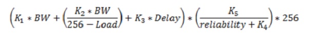
It's pretty complex and I can assure you that it's fairly impossible to figure out this in your head when looking at a topology. It's almost not even worth trying this manually, but for those that dare just follow the formula above. As you can see the metric weights are called K-values which means how much each metric value is "weighted" in the formula. Increasing a metric weight therefor doubles that K-value in the formula.
But lucky for us, only Bandwidth and Delay are used by default and that simplifies the above formula very much! Here's a much easier way to calculate the metric when default metric weights are used:
Pretty much it involves just calculating the Bandwidth metric and the Delay metric, add their computed value together and multiply them by 256. That is somewhat easier to partially do in your head.
It all depends on the initial Bandwidth and Metric values. What is difficult here is that the Bandwidth uses kbps (that is KiloBits Per Second) and the Delay uses Tens of Microseconds. Let's look at how much easier this can be.
The bandwidth, since it is meassured in kbps, means that in Step 1 above we can use the formula 10,000,000/bandwidth to get the bandwidth value. Why is this so much eaiser?
Because let's assume you have a 10Mbit/s as the slowest link. That means the bandwidth is 10,000kbps (easy enough, just add three 0's to get the kbps from mbps). Now the bandwidth formula is simply: 10,000,000/10,000. The math here is simple: 10^7 - 10^4 = 10^3 = 1000.
What should be noticed here is the fact that the calculated bandwidth value was 1000, which is only a zero (0) less than the original 10,000kbps. So by default it's very easy to see the Bandwidth Metric.
For a 10mbps connection the bandwidth in kpbs is 100,000. 10^7-10^5=10^2 =100.
What happened there? Yes the metric for the bandwidth is DECREASED with a higher speed connection.
Simplified the metric for the various connections are:
1mbps = 10000
10mbps = 1000
100mbps = 100
1gbps = 10
10gbps = 1
This means that for any connection higher than 10gbps EIGRP doesn't scale properly since the BW-value will not function properly.
Now for the delay value this is not as simple. But the default delay on different interfaces are like in this picture: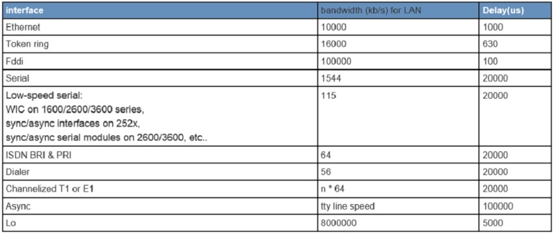
Note: This picture is not complete, the picture assumes a 10mbps ethernet link. A 100mbps ethernet link has a delay of 10, a 1gbps link has a delay of 1. The delay of the 10mbps ethernet link in the picture above assumes "tens of microseconds" and the actual delay should be 100, but we need "tens of seconds" (multiply by 10) so therefor it displays 1000.
If anything should be remembered it is that the Ethernet has a delay of 1000 and the Serial-links have a delay of 20,000. Other than that, there is no need to know the others since you can just look at the interface to see the value if that's needed.
What you would have to do is add all the delays along the path from all outgoing interfaces and then simply divide them by 10 to get the Delay metric. So let's say we are going to a route that is two hops away over a serial interface and an ethernet-link, then the total delay would simply be 20,000+1000=21,000.
Just divide 21,000 by 10 to get the metric of 2100.
The final piece of the puzzle is to just add the metric for the Bandwidth and the Delay together. So if the slowest link was a 100mbps the total metric would be 100 + 2100 = 2200.
That metric would probably be fine as it is, however there is an offset by multiplying this by 256 to get the final metric - which is why it's called the composite metric.
So 256 times 2200 = 563200 as the final metric that EIGRP will have for that route.
As you can see, don't expect to be able to do this manually in your head. That last calculation will still be extremely difficult to do.
Special note: If it wasn't clear with the above example it means that a higher speed link will mean a lower delay value, a higher slowest bandwidth value will mean a lower bandwith value. Together this will "shrink" the metric so to speak. Ultmately choosing the "best path" with the lowest metric which doesn't nessecarily mean the fastest links or the links with the lowest delays. It chooses the path that has the best composite metric!
EIGRP Wide Metric
All the above refers to the Classic EIGRP Metric Calculation. This section continues the concept of discussing why there was a need for the Wide Metric calculation.
What I was trying to make clear with the above calculations and metric discussion was that EIGRP doesn't scale with interfaces above 1gbps because it would not be able to determine any difference in delay between a 1gbps interface and a 10gbps interface. The bandwidth metric would not be able to tell any difference between a 10gbps link and a 40gbps link.
Simply put, with todays network speeds EIGRP has reached it's scalability limits. So the solution was to invent what is called the "Wide Metric" formula". Which basically is the same formula as above with a few additional tweaks as follows:
-The Bandwidth value is now called Throughput and the only change is that the start-metric is multiplied by 65536 to simulate a 655.36Tbps link as the reference bandwidth.
-The Delay value is now called Latency (makes much more sence) but this calculation is changed to the worse. The formula is now: 65536xInterface Delay/10^6. The worse part is that the Interface Delay value is now meassured in picoseconds. Making this much more difficult to do the math.
Luckily for us, the IOS simplifies this by checking if the interface is of higher speed than 1Gbps before doing the math above. The rules are:
-For interfaces operating at 1Gbps or lower speeds the EIGRP process simply takes the default delay value and converts it to picoseconds.
-For interfaces operating at speeds over 1Gbps the EIGRP process takes the default interface value ^13 and divides it by the default interface bandwidth value.
-For interfaces with manually configured bandwidth value, the default delay value is converted to picoseconds.
-For interfaces with manually configured delay value the delay value is calculated by 10^7xconfigured delay value.
All in all this makes the metric scale much, much better with modern networks and it makes slower networks really get a much higher composite metric.
The other values remain the same, with one addes K-value for future usage, it's not supported and not included in the certification exam but it is worth meantioning that there is a K6-value with EIGRP Wide Metric that is reserved for future usage. Such as Jitter etc.
That leaves only the final part of providing an example. So let's stick with the same bandwidth and delay as from the Classic example. To recall, the metrics that were used were:
-100mbps link
-21000 latency total (1 ethernet link and 1 serial link)
The Bandwidth formula is 65536x10^7/Interface Bandwidth. So in this case of 100mbps the formula is: 65536*10^7/10^6 = 65536*10/1 = 655,360.
Once you understand the logic it's pretty easy to see that all you have to do is add 0's to the value of 65536. The number of's to add depends on the math between 10^7-10^x where X is a number depending on your interface bandwidth. The remainder is how many 0's to add.
Note: This math only works with normal bandwidth links, not with serial links or other slow-links.
Simple enough it means that its <= 1Gbps link so the default interface delay value is a total of 2100. Convert this value to picoseconds 2100*10^7=21,000,000,000. This is a very high Latency value!
The final piece is to add the sum from the Throughput value and the Latency value together and multiply them by 256:
(21000000000+655,360)*256 = 53,761,677,72,160.
Wow that is a pretty insane metric, wouldn't you say?
Now there is a problem, the RIB (Routing Information Base) will only support 32-bit numbers so the IOS will actually convert it before storing it in the RIB since the RIB will support between 32-bit to 128-bit metric-values, depending on IOS versions and features.
The IOS scales this metric to the RIB by dividing it by 128 (default value) which is also manually adjustable with the command "metric rib-scale EIGRP" command.
Note: The EIGRP will ONLY use the calculated insanley high composite wide-metric value for deciding which path to put in the routing-table. This scaling is only done so the route can be installed in the RIB to convert it to a 32-bit value.
Modifying EIGRP Vector Attributes
-As discussed in the calculation examples above the Metric values are so called K-values and depending on the configured values they weight differently. There is nothing more to this part of EIGRP other than that you can manually adjust the "weights" of the metric calculation with this command:
router eigrp 1
metric weight 0 1 0 1 0 0
router eigrp CCIE
address-family ipv4 unicast autonomous-system 1
metric weights 0 1 0 1 0 0 <optional K6>
The first 0 is the ToS field which is a QoS value which should most likely be set to 0, then follows the K1 , K2, K3, K4, K5 values. This causes the adjacencies to re-form with new metric-values so use with caution!
EIGRP Equal Cost Load Balancing, EIGRP Unequal Cost Load Balancing
-When there is a tie in the metric there is a chance that EIGRP will install two routes to the same network, in that case the EIGRP process will perform Equal Cost Load Balancing.
Meaning that there are two equal cost-paths to reach a destination, so do load-balancing towards that destination network.
But EIGRP is also the only protocol that will do so called Unequal Cost Load Balancing. This means that EIGRP can do load-balance to a remote destination network when the metric value is not the same for a network.
For the Unequal Cost Load Balancing to work the requirements are that there must be a backup-route existing in the EIGRP Topology, in EIGRP terminology that is a Feasable Successor.
So as long as the EIGRP topology has a feasable successor for a route it's possible to install that in the routing-table and perform Unequal Cost Load Balancing.
This is done through the "variance" command which tells the IOS Router to only install EIGRP routes in the Routing-table that has a highest-default metric of 1 times the current successor. In other words this means that as long as the variance is set to 1, only the best path / lowest metric path will be used.
Load balancing will only be performed as long as the router has at least two equal cost paths to the destination network. By increasing the variance command you are basically telling the router "how much worse of a route than my primary route should I install in the routing-table?".
The variance command is a multiplier of the primary route (the successor route). So if the successor route had a metri of 100,000 and the variance command was set to 3. The router would install routes with as bad metric as 300,000 as long as it's a feasable successor.
Remember that the Feasable Successor is a route where the Advertised Distance is less than the current primary distance. Meaning in this case as long as a neighboring router advertises that they can reach this route with a metric lower than 100.000 it will be installed in the routing-table.
EIGRP Add-Path
-This is a very new feature introduced in IOS 15.3 which is a feature designed to solve a problem with Hub-and-Spoke topologies. In modern networks it's usually that the spokes have two paths to reach the hub. Called a Dual-homed configuration.
In that case the Hub would only install a single route to the spokes and not both the paths. That's where the Add-Path configuration applies. It only works in Named-Mode and it doesn't support Unequal Cost Load Balancing. This assumes that Equal Cost Load Balancing is effective, so metrics needs to be the same.
This sure does look like normal ECMP. However this command was intended to be used on the Hub-router where there could be multiple ISPs connecting to all the spokes.
That's where the add-path command solves the problem of taking routes learned on tunnel interfac 1 and put them in tunnel interface 2 and use them both for load-balancing.
For this to work, the "no next-hop-self" command has to be configured because otherwise the wrong next-hop address would be used when the route is advertised to the downstream spokes!
The best way to describe when Add-Path is useable is by looking at this image:
In this topology there is a redundancy with the Dual Hubs and spke 3-4 and 1-2 are back-to-back connected in a LAN. They are also Dual-homed since they connect to different ISP's back towards the Hubs.
This is a special case where EIGRP would not advertise all paths but rather pick a best path, mainly because the metric would not be the same although both paths are actually usefull to the 192.168.1.0/24 and 192.168.2.0/24.
To use both paths, the EIGRP Add-Path was invented so that the Hubs could advertise about all the paths to the spokes. For example, the path towards network 192.168.1.0/24 advertised towards spoke 3-4 would mean that either the link through SP1 or SP2 would be used. With Add-Path both links could be used.
EIGRP Authentication, EIGRP MD5 Authentication
-EIGRP Authentication works the same as with RIP. It does not encrypt the packets but it prevents DDoS attacks since it's impossible to form an adjacency between two routers unless the MD5-hash matches.
The concept is the same and all you would have to do is tell the interface which authentication-mode to use and which authentication-key to use. Therefor it's required to use a key-chain to configure the key-ids and the key-strings first.
MD5-authentication is supported in both Named Mode and Classic mode. There is no difference in how it works, however in Classic mode every single interface needs to be configured for Authentication but in the Named Mode it's possible to set a default-authentication for all interfaces at once!
Example with Classic EIGRP:
router eigrp 1
network 0.0.0.0 255.255.255.255
exit
key-chain EIGRP
key 1
key-string CCIE
end
conf t
int fa0/0
ip authentication eigrp 1 mode md5
ip authentication eigrp 1 key-chain EIGRP
Example with Named Mode EIGRP:
key-chain EIGRP
key 1
key-string CCIE
router eigrp CCIE
address-family ipv4 autonomous-system 1
af-interface default
authentication mode md5
authentication key-chain EIGRP
exit
As with RIP it's a key thing to remember here that the key-id and the key-string are part of the MD5-hashing algorithm so if they don't match the MD5 hash doesn't match and the authentication will fail.
EIGRP SHA-256 Authentication
-SHA-256 authentication is also called the Second Generation SHA-authentication, or simply SHA-256.
This mode is only supported in Named Mode and this mode also supports both the Key-Chain feature or you can simply add a password under each interface.
The only difference is that there is no Automatic Key-Rollover if you don't use the Key-Chain feature.
The configuration is straight-forward:
key-chain EIGRP
key 1
key-string CCIE
end
conf t
router eigrp CCIE
address-family ipv4 autonomous-system 1
af-interface default
ip authentication mode sha hmac-sha-256 <any dummy password is required here!>
authentication key-chain EIGRP
Note: that it's required to enter a password to even enable SHA-256 however we are using the key-chain feature so the password is not used, therefor it's called a "dummy password".
Special note about INE: If you are watching older versions of the INE-videos for this topic you will learn that the key-chain command is not supported for SHA-256 authentication. In fact it is, so don't be fooled by that!
EIGRP Automatic Key Rollover
-The terminology Automatic Key Rollover simply means that you configure more than one key in the key-chain command. Each key is valid for a certain timeframe and then you migrate away into the new key.
This is pretty straightforward and the only caveat is that you have to make sure that during the migration process between two keys, for a short timeframe both keys must be valid or EIGRP adjacencies will cease due to invalid authentication. This only happens if the routers try to speak with each other during the migration process.
The most common mistake there is to configure one key to end at 23:59:59 and the other key to start at 00:00:00 the next day. Although a tiny small window exists where there are no valid keys, all it takes is for EIGRP to speak with eachother during that timefram and they will re-form adjacencies because the authentication failed.
To understand how to properly configure a key Rollover it's a must to understand how the router chooses the key to use for authentication:
-The EIGRP will choose it's lowest valid key-number when sending messages.
-The receiving EIGRP router will then try to validate the message based on the same key-number.
In other words, the key-numbers would have to match at all times between the sending router and the receiving router. For an automatic key rollover to actually work, it's essential to manually configure the accept-time of a key and the send-time for a key. The design goal here is to start sending with a different key slightly earlier then you stop accepting the old key.
From a design perspective this means that you need to have two valid keys for a small timeframe, usualy a second or two will be enough. The reason is obvious, if one router starts to send authentication with a new key-number the receiving router must have the same key-number and accept incoming authentication messages with that key. At the same time that router might send with the other key, so both routers would need two valid keys for a short time.
A configuration example with automatic key rollover between two routers:
!R1
key-chain EIGRP
key 1
accept-lifetime 01:00:00 Dec 24 2015 13:01:00 Dec 31 2015
send-lifetime 01:00:00 Dec 24 2015 13:00:00 Dec 31 2015
key-string CCIE_1
lifetime
exit
key 2
accept-lifetime 13:00:00 Dec 31 2015 13:01:00 Jan 07 2016
send-lifetime 13:00:00 Dec 31 2015 13:00:00 Jan 07 2016
key-string CCIE_2
!R2
key-chain EIGRP
key 1
accept-lifetime 01:00:00 Dec 24 2015 13:01:00 Dec 31 2015
send-lifetime 01:00:00 Dec 24 2015 13:00:00 Dec 31 2015
key-string CCIE_1
lifetime
exit
key 2
accept-lifetime 13:00:00 Dec 31 2015 13:01:00 Jan 07 2016
send-lifetime 13:00:00 Dec 31 2015 13:00:00 Jan 07 2016
key-string CCIE_2
Note: The key thing here to understand is that the configuration will stop sending with key 1 at the breakpoint of 13:00:00 Dec, 31 2015. It will then start sending with key 2 at 13:00:00 Dec, 31 2015.
This will not be causing any trouble because key 1 will still be accepted on received messages for an additional 1 minute from when the routers will start sending with key 2. And there is combination of sending and receiving accepted keys that would cause authentication to fail.
If you are really worried about your NTP-servers not beign synchronized well enough, it's probably better to tweak down the accepted lifetime on the new key (key 2 in this example) to start accepting that key at about 12:59:00 Dec, 31 2015 instead of 13:00:00.
Just remember that The router will send with the lowest valid key, and the receiving router will authenticate using this same key. So if a router can send with key 1, the other router must be able to authenticate using that key. Simple as that!
Additional design note: The general best practice here is actually to overlap both the sending and the accepting lifetime in both directions, however since the router is only ever going to be sending the lowest accepted-key it makes only sense to extend the accepted-timeframe of the previous key....since the router will always be sending the lowest key, and when you switch keys you might under very rare circumstances be sending the wrong key (due to how the time actually works) so always be sure to overlap the accepting timeframe of the keys.
Time Required: 7 hours 30 minutes. - Watched the INE CCIE Videos about:
-EIGRP Initialization
-EIGRP Network Statement
-EIGRP Multicast vs Unicast Updates
-EIGRP Named Mode
-EIGRP Multi AF Mode
-EIGRP Split-Horizon
-EIGRP Next-Hop Processing
-EIGRP Path Selection
-EIGRP Feasibility Condition
-Modifying EIGRP Vector Attributes
-EIGRP Classic Metric
-EIGRP Wide Metric
-EIGRP Metric Weights
-EIGRP Equal Cost Load Balancing
-EIGRP Unequal Cost Load Balancing
-EIGRP Add-Path
-EIGRP Authentication
-EIGRP MD5 Authentication
-EIGRP SHA-256 Authentication
-EIGRP Automatic Key Rollover
Time required: 5 hours 15 minutes. - Did the following labs (Advanced Technology Labs) from the INE RSv5 workbook:
-EIGRP Network Statement page 356.
-EIGRP Auto-Summary page 365.
-EIGRP Multi-AF Mode page 369.
-EIGRP MD5 & SHA-256 Authentication page 373.
-EIGRP Key Chain Rotation page 382.
-EIGRP Unicast Updates page 390.
-EIGRP Metric Weights page 416.
-EIGRP Traffic engineering with Metric page 420.
-EIGRP Unequal Cost Load Balancing page 423.
Learned:
-Using the command "no ip split-horizon" did not disable the split-horizon feature, instead the full command needs to be used to include the EIGRP process in the command. "no ip split-horizon eigrp 100".
-If only delay is used as the metric weights, it's fairly easy to calculate the total delay. Use various show commands and add the delay along the transit path. Then divide by 10 (or remove a 0) and scale by 256.
-To configure unequal load-balancing make sure that the feasability condition is met. If asked by a task to configure a certain traffic-share count for the load-balancing, like a 5:1 ratio, it's a direct 1:1 related ratio between the route-metrics.
So to send 5 times more packets over one route it's metric needs to be exactly 5 times higher.
I find the easiest way to solve these type of issues is to use either route-maps to set the metric or offset lists to get the desired metrics. It's also possible to manipulate the delay or bandwidth parameters along the paths, as long as it meets the design requirements and there are no specific restrictions against using either method - then solve the problem anyhow.
Time required: 3 hours.
daniel.larsson- Admin
- Posts : 47
Join date : 2015-04-30
Age : 41
Location : Boras, Sweden -
Layer 3 - Enhanced Interior Gateway Routing Protocol PART 2
![]() by daniel.larsson Wed Jun 17, 2015 2:44 pm
by daniel.larsson Wed Jun 17, 2015 2:44 pm
Technology:
- EIGRP Summarization
- EIGRP Auto-Summary
- EIGRP Manual Summarization
- EIGRP Summarization with Default Routing
- EIGRP Summarization with Leak Map
- EIGRP Summary Metric
- EIGRP Convergence Optimization & Scalability
- EIGRP Convergence Timers
- EIGRP Query Scoping with Summarization
- EIGRP Query Scoping with Stub Routing
- EIGRP Stub Routing with Leak Map
- EIGRP Bandwidth Pacing
- EIGRP IP FRR
- EIGRP Graceful Restart & NSF
Enhanced Interior Gateway Routing Protocol PART 2
(EIGRP Summarization, EIGRP Auto-Summary, EIGRP Manual Summarization, EIGRP Summarization with Default Routing, EIGRP Summarization with Leak Map, EIGRP Summary Metric, EIGRP Convergence Optimization & Scalability, EIGRP Convergence Timers, EIGRP Query Scoping with Summarization, EIGRP Query Scoping with Stub Routing, EIGRP Stub Routing with Leak Map, EIGRP Bandwidth Pacing, EIGRP IP FRR, EIGRP Graceful Restart & NSF)
Notes Before reading: This section is also fairly long due to all the topics to be covered in this part. Many topics overlap with both CCNA and CCNP so there is not much new information to take in here.
EIGRP Summarization, EIGRP Auto-Summary, EIGRP Manual Summarization, EIGRP Summarization with Default Routing, EIGRP Summarization with Leak Map, EIGRP Summary Metric, EIGRP Convergence Optimization & Scalability, EIGRP Convergence Timers, EIGRP Query Scoping with Summarization, EIGRP Query Scoping with Stub Routing, EIGRP Stub Routing with Leak Map, EIGRP Bandwidth Pacing, EIGRP IP FRR, EIGRP Graceful Restart & NSF
- Again many of these topics will overlap with CCNP and some is even overlaped with CCNA. There are some new more advanced topics that is new for CCIE, mainly Bandwidth Pacing, Leak Maps and IP FRR. Every other topic in this section is actually covered in CCNP R&S. Maybe not at CCIE-level of understanding, but the foundation and basics are there which makes this a rather difficult topic to study CCIE for since there are not that many ways you can alter these technologies.
I have a really good understanding of all the sections below, but for my study notes i will also do a brief explanation of each topic just to make sure to cover them all.
The ROUTE-book covers most CCIE topics of EIGRP. What it doesn't cover is the new IOS 15.0 features and configuration syntax. Basically it covers exactly everything that's in the EIGRP blueprint except the new 15.0 features, so by reading and learning what's in this book you have covered 85% of the EIGRP topics.
Book: CCNP ROUTE Official Certification Guide, chapter 3-4.
Chapter 3 is named: EIGRP Topology, Routes, and Convergence.
Chapter 4 is named: EIGRP Route Summarization and Filtering.
What's not covered in the ROUTE book is the new 15.0 IOS features for EIGRP, and that requires to read a bit in the CCIE RSv5 Official Certification Guide as well. We are mainly interested in looking at the 15.0 features here, so I'm keeping it towards EIGRP Named Mode, EIGRP Multi-AF Mode of all the topics listed above.
Book: CCIE RSv5 Official Certification Guide, Chapter 8.
Chapter 8 is named: EIGRP
EIGRP Configuration Guide Link: http://www.cisco.com/c/en/us/td/docs/ios-xml/ios/iproute_eigrp/configuration/15-mt/ire-15-mt-book/ire-enhanced-igrp.html
EIGRP Nonstop Forwarding (NSF) Awareness: http://www.cisco.com/c/en/us/td/docs/ios-xml/ios/iproute_eigrp/configuration/15-mt/ire-15-mt-book/eigrp-nsf-awa.html
Note: Not all of the things I write down here are actually learned, but like with RIPv2 I am writing down good-to-have study notes that I can use to easily come back and study these topics again before the actual Lab-exam.
Learned:
EIGRP Summarization, EIGRP Auto-Summary, EIGRP Manual Summarization
-EIGRP Summarization is easy with EIGRP.
-EIGRP by Default uses the Auto-summary (IOS prior to 15.X) feature of the protocol which means that it will work just the same way that RIPv2 does. In other words it will do auto-summary when routes are moving from one major network domain into another major network domain.
This also means that by default EIGRP does not support Discontigous networks unless the transit path is in the same Major network domain. As long as the router is advertising it into another major network domain it will be summarized into the old default classfull-mask.
Note: In the new IOS version 15.X the default is to have auto-summary disabled! Finally ;-).
-But since EIGRP is a Distance Vector protocol you can send a summary out any interface, at any point in the EIGRP topology. All you would have to do is figure out which summary-address you want to advertise and go into the interface where you want to advertise that route. Then configure your summary-address and it will be sent out that interface to other EIGRP Neighbors.
By default this will create a summary-route to the null0 interface in the routing table with an Advertised Distance of 5, if another value is required it must manually be configured during the summary-address advertisement under the specific interface.
Note: In IOS releases prior to 15.0 it's possible to manually alter the summary-address AD value when creating the summary. This feature is removed in the 15.0 release and is no longer available. To modify the AD value of the summary route other methods must be used. It is replaced by the "summary-metric x.x.x.x/y distance AD" command.
An example to summarize networks 192.168.0.0/24 and 192.168.1.0/24 into 192.168.0.0/23.
EIGRP Classic Example:
router eigrp 1
network 192.168.0.0 0.0.0.255
network 192.168.1.0 0.0.0.255
exit
interface fa0/0
ip summary-address eigrp 1 192.168.0.0 255.255.254.0
EIGRP Named Mode Example:
router eigrp ccie
address-family ipv4 unicast autonomous-system 1
network 192.168.0.0 0.0.0.255
network 192.168.1.0 0.0.0.255
af-interface fa0/0
summary-address 192.168.0.0 255.255.254.0
This will create a summary-address of 192.168.0.0/23 that will point to the interface Null0 in the routing table with an AD-value of 5. The router will then start to send this summary-address out interface fa0/0.
What is worth noting here is that this summary-address is NOT sent out any other interfaces since it's not configured to do so. However in the named-mode you could send the summary-address out in the default-interface mode which would send it out every interface at the same time.
EIGRP Summarization with Default Routing
This is as simple as it sounds, all this means is that you send a summary-route out a specific interface that becomes a default-route.
In other words, advertise network 0.0.0.0 0.0.0.0 out that interface.
EIGRP Classic Example:
router eigrp 1
network 192.168.0.0 0.0.0.255
network 192.168.1.0 0.0.0.255
exit
interface fa0/0
ip summary-address eigrp 1 0.0.0.0 0.0.0.0
EIGRP Named Mode Example:
router eigrp CCIE
address-family ipv4 unicast autonomous-system 1
network 192.168.0.0 0.0.0.255
network 192.168.1.0 0.0.0.255
af-interface fa0/0
summary-address 0.0.0.0/0
Configuration Note: In the 15.0 release we can finally use CIDR-notations instead of decimal! E.g 0.0.0.0/0
This will create a default route of 0.0.0.0/0 towards the Null0 interface and the EIGRP 1 process will then advertise this route out to neighbors on interface Fa0/0.
Caution note: When advertising a default route with AD 5 this means that since it has AD5 it might be replacing the current default-route in the routing-table of this router. It all depends on how the default-route is known to the router.
For example:
If the router currently knows about a default-network of 0.0.0.0/0 through RIP (AD 120) that points towards another router, creating the summary route of 0.0.0.0/0 and advertising it through eigrp without specifying a higher AD value than 120 will create a blackhole-routing that points to interface Null0 for 0.0.0.0/0 networks. In other words, if the default route points towards this router it will be blackholed unless the AD value is changed.
Design Note: This is just an extreme case where the router already has a default route that points towards one routing domain. By creating a new default-route using the summar-address commands of EIGRP it will automatically install a route to the Null0 interface causing the local router to have a blackhole-route towards Null0 for the default route.
EIGRP Summarization with Leak Map
-When you summarize a network manually, that summary-route will be the only route that is being advertised out that interface. This helps to reduce the routing-table and limit the query-scoping (more on that in a later section). But this also means that the neighboring route will not learn any specific routes that is included in the summary-route.
So in case you need to do some kind of traffic engineering with a specific route, that route must first somehow be placed in the routing-table via static route to the Null0 interface with a more specific mask.
That will work, but a much better sollution would be to allow specific routes to be advertised along with the summary-route. This is done with something called a Leak-Map.
A Leak-Map is basically a route-map that will permit the more specific routes along with the summary-route. In other words you must create an access-list, extended or standard, that will capture the specific routes that you want to allow through and then link them to the route-map. Of course the prefix-list is also supported, basically anything that you can match against in the route-map is allowed.
The route-map is then called under the summary-address command in interface-mode with the Leak-Map parameter. So a configuration example will send out the summary route 192.168.0.0/22 and the specific network of 192.168.3.0/24.
Classic EIGRP Example:
conf t
ip access-list 1 permit 192.168.3.0 0.0.0.0
route-map LEAKED_ROUTES permit 10
match ip address 1
end
conf t
router eigrp 1
network 192.168.0.0 0.0.3.255
exit
interface fa0/0
ip summary-address eigrp 1 192.168.0.0 255.255.252.0 leak-map LEAKED_ROUTES
EIGRP Named Mode Example:
ip access-list 1 permit 192.168.3.0 0.0.0.0
route-map LEAKED_ROUTES permit 10
match ip address 1
end
conf t
router eigrp CCIE
address-family ipv4 unicast autonomous-system 1
af-interface fa0/0
summary-address 192.168.0.0 255.255.252.0 leak-map LEAKED_ROUTES
That's it. What this accomplishes is that we are sending the summary-route 192.168.0.0/22 out interface fa0/0 but we are also allowing the specific route of 192.168.3.0/24 to be leaked out that interface.
This is because we are catching the specific route with the standard ACL 1 (permit 192.168.3.0 0.0.0.0 means capture the network route for 192.168.3.0) we are matching that with the Route-map which has a permit clause.
Caution Note: Be careful when using the route-map for leak-maps, becuase in this case there is only a sequence 10 in the route-map. But adding a sequence 20 with just a permit statement that doesn't match any ACL's would mean every route would be leaked.
EIGRP Summary Metric
-The EIGRP summary Metric is simple. Just take the lowest composite metric among all the routes that is included in the summary-route. For example:
If network 192.168.0.0, 192.168.1.0, 192.168.2.0 and 192.168.3.0 has a metric of 1,2,3,4 respectively. The summary-route of 192.168.0.0/22 would have a metric of 1 since that is the lowest composite metric among all the routes that are summarized.
If that route is no longer available, the EIGRP process would have to look through all the routes again to pick the lowest composite metric. This can cause CPU and Memory issues if the topology is large and the summary includes a lot of routes.
For older IOS-release there is no solution to that problem, but with EIGRP running in Named Mode there is a solution to statically specify the metric for the summary route - ultimately preventing the router from having to do manual composite metric lookup inside the summary-range when a route inside the summary-range is no longer available.
EIGRP Named Mode Example assign static summary metric with AD 95:
router eigrp CCIE
address-family ipv4 unicast autonomous-system 1
topology base
summary-metric 0.0.0.0/0 100000 100 255 1 1500 distance 95
In this case we are modifying the default metric in the default-route summary to the values listed above.
Note: This command actually does nothing in the above example, becuase we don't have the summary route of 0.0.0.0/0 installed in the routing table. So you must first make sure that the route is in the routing-table before using this command.
EIGRP Convergence Optimization & Scalability, EIGRP Convergence Timers
-EIGPR is a Distance Vector protocol and therefor uses the concept of Split Horizon, Split Horizon with Poison Reverse and Hold-Down timers to try and prevent routing-loops.
-Also EIGRP uses the concept of Hellos and Hold Down timer to determine if a neighbor is alive or down. Typically everytime a neighbor receives a hello-packet from a neighbor, it resets the holddown timer for that specific neighbor.
If the Hold-Down timer expires, the neighbor is considered down and the adjacency is flushed and all routes that used to be routed through this neighbor is also considered to be down. In this case EIGRP needs to reconverge, getting new information about lost routes and hopefully find an alternative path to the lost routes.
And if the neighbor comes back up, the adjacency is formed again and routes exchanged as usual (with full topology exchange during startup, followed by partial updates when needed).
The timers that EIGRP uses by default are different depending on the Segment it is connected to. In general these timers are used:
-LAN Connections: EIGRP Hello packet every 5 seconds, Hold Down timer 15 seconds.
-WAN Connections: EIGRP Hello Packet every 60 seconds, Hold Down timer 180 seconds.
As can be told by the above math, the convergence is pretty slow and it takes EIGRP as long as 15 seconds to detect that a neighbor is down in a LAN-segment and 3 minutes!! In a WAN-section.
Obviously these timers are not very fast in a modern network, so they can - and should - be tuned down to fit your network design. By default these timers don't scale well on WAN-connections and the reason these timers are set so high is because they were designed back in the days when it was common to have extremely slow WAN-links like 128kbps and so on.
EIGRP Classic Example modifying default convergence timers:
router eigrp 1
network 0.0.0.0 255.255.255.255
exit
interface fa0/0
ip hello-interval eigrp 1 1
ip hold-time eigrp 1 3
EIGRP Named Mode Example modifying the default convergence timers:
router eigrp CCIE
address-family ipv4 unicast autonomous-system 1
network 0.0.0.0 255.255.255.255
af-interface default
hello-interval 1
hold-time 3
In this example we configure the hello-interval to be 1 second and the hold-down time to be 3 seconds. In the classic mode we must configure this for every single interface, in the named mode we can configure this as the default-value for all interfaces.
Interesting Design/Configuration Note: What is interesting about this configuration is that the "hello-interval" tells the local router how often to send out a hello-packet to it's neighbors. But the "hold-time" is actually telling the remote-router how long to wait before considering the advertising neighbor to be down.
Since these values don't have to match for EIGRP to work, it's perfectly fine. But if you are asked to set the hold-time timer on R3 to let's say 5 seconds instead of 15 seconds. Then you would have to be careful, since the hold-down timer is configured from the remote-router since this is a timer that is advertised in the EIGRP-hello packet so that the other neighbors know which value to use on that link!
EIGRP Query Scoping with Summarization
-EIGRP also uses the concept of Queries to try and ask neighbors if they have a path for the failed route. During normal operations this isn't a problem, but when it comes to scalability this can become a problem because in some network topologies and designs you will see that EIGRP has a lot of trouble dealing with this feature.
Active in EIGRP means that the router is actively searching the network for a route towards this network. In other words, it's asking it's neighbors with a query if they have a path for this route.
Passive in EIGRP means that the router knows how to reach this network and that the router is not asking it's neighbors how to reach this network. In other words, it's not sending any queries!
By default when a route becomes "active" it means that the router will try and ask it's neighbors that they have formed an adjacency with. At the same time a timer of 3 minutes starts, which is the "Active Timer". If the router does not receive a query-reply back in 3 minutes the router resets the process and sends queries again. What I mean by this is that the router will reform-the adjacencies with the neighbors that didn't reply to the query-packets. Typically this will cause a network-wide outage since the quries will bounce across the entier network domain by default.
The problem is that if this 3 minute timer expires the router will reset the adjacency with this neighbor that didn't reply, causing a complete data-plane outage!
-Whenever two EIGRP routers become neighbors, they have formed an adjacency with each other. Remember that EIGRP doesn't care if the subnet mask on both sides of the link is the same as long as both ip-addresses appears to belong to the same subnet (.1/24 and .1/30 for example).
The purpose of this Adjacency is to send unicast update information to each other, and to keep track on the other neigbor in case it looses the link towards that neighbor. But another, hard to find feature, of the adjacency is that when an EIGRP router looses a link that network will go down. The router will then use it's EIGRP-neighbors to start query them for information about the route that they just lost.
EIGRP is dumb in this manner. With that I mean that the neighbor could've stopped there and either replied with a "yes" or a "no" and the query would not cause a problem. However this is not the case, the neighboring router will then in return also ask it's own neighbors about this route.
With default configuration and no summarizations this will be a network-wide query that will ultimately reach all router sin the EIGRP domain. The problem here is that since that query spread like a plague across the EIGRP-domain every router that SENT a query-request would HAVE TO WAIT for a reply from the neighbor they asked!
This is really the problem, because the router that first lost the link and the route may be 50 routers away from the other end of the network-topology and it would have to sit there and wait until every router has gotten a query-reply.
As you can imagine this is not very effective and is not a good way to solve a reachability problem. Especially in certain topologies this will cause the EIGRP routers to become "stuck in active".
"Stuck In Active, SIA" is a CCNP topic that was moved down from CCIE ;-). However this terminology means that the router is Stuck in the Active process. In other words the network topology and design does not support Queries well, so the routers will just send the queries around in a circle until the router figures out that it won't get a reply and resets the process. Technically it will not send the queries around in circles, but at some point your network will become so large that the 3 minute timer is not enough to wait for replies from the whole network domain.
This will not happen in a well designed network, or not in many networks at all. For this to happen you have to basically have a very very bad network design with stub-routers connected to other stub routers that at some point links back into the core-network again.
Note: With stub-routers here i just mean that they should be configured as stub-routers, but they aren't.
Finding a good topology example for this subject is difficult, because all it really takes is a slow network end-to-end reachability that will cause the originating query router to have to wait for the full duration of the active timer. When this happens the router will reset the adjacency with that router.
An example topology: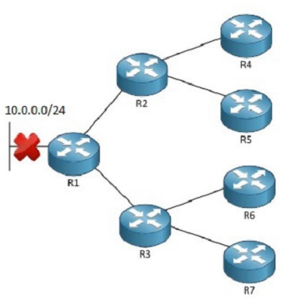
This probably wouldn't cause any routers to become Stuck in Active. However when the 10.0.0.0/24 network fails at R1 it will ask R3 and R2 about this network. They don't know about this network, so they will ask their own neighbors about this network. R4-7 also doesn't know about this network so they will reply back to R2 and R3. R2 and R3 will then finally reply back to R1 informing R1 that there were no routes available for the lost 10.0.0.0/24 network.
The key point here to understand is that when R1 asks R2 and R3 with a query, a 3 minute timer will start to count against R3 and R2. If they don't reply back within 3 minutes R1 will reset the adjacency with them.
The sollution to this problem is to prevent R3 and R2 from sending queries out to R4-R7. You do this by sending a summary-route from R2 and R3 up towards R1 that includes the 10.0.0.0/24 prefix.
The problem with this topology is that it looks like R1 normally would be a Stub-router, but in this case it seems like it lost it's connection to a WAN or something else. The idea remains the same though. Normally you design your topology in a hierarchical way so that you can summarize your topology in a good way.
The idea is that you need to make R2 and R3 have a summary-route that includes the queried prefix, so that they will reply back with a "no, i don't have this route" instead of asking it's neighbors. For example from R2 and R3's perspective they don't need to know the specific /24 subnets in the 10.0.0.0/8 range, but they need to know a summary-address that includes at least the failed 10.0.0.0/24 prefix.
In this case there is no way to solve the issue with a summary-route because you could only limit the query scop on either R2 or R3, not both. But let us assume that there are more links from R4-7 that completes the topology so that you can reach R1 from all R4-R7 routers. Then this summary from R2 and R3 would solve the problem:
10.0.0.0/16.
When R1 asks R2 and R3 they will reply with a "no" back, and also not send any queries downstreams since the 10.0.0.0/24 prefix was included in the summary-route that R2 and R3 have in it's routing table.
The better way to solve it in this case is to simply say that R1 is a EIGRP-STub router, since there is no router attached to R1 they are considered Stub-routers. The same goes for R4-R7, no other routers are reachable past them so they should be configured for Stub-routers.
EIGRP Query Scoping with Stub Routing
-When there is a router in a topology which does not link to another router, it is considered a Stub-router. From the perspective of EIGRP this means that there is no router attached to the Stub-router, so why should I send Queries to it when I already know about all it's routes?
Take the following topology again as an example:
This time we have configured R1 and R4-R7 as stub-routers using the command:
router eigrp 1
eigrp stub
Configuration Note: The EIGRP Stub-command is configured on the stub-routers themselves, and have several parameters which will be shortly explained below. When you enter the "eigrp stub" command on a router, it will tell that router to become a Stub-router and not advertise about any routes to upstream routers. Of course it will still advertise about routes, however it is a stub-router so it would not know too many routes as we will learn.
It will also tell it's upstream routers that this router is an EIGRP Stub-router. The router will do this by setting the EIGRP Stub-flag, which is easiler explained by looking at the EIGRP-packet:
As we can see by this picture, that explains how the EIGRP Packet should look like, it contains a field for Flags. Flags are typically EIGRP specific flags that the protocol can set to do special things.
When we are talking about EIGRP Stub-Routers we are talking about using the Flag-field to tell our upstream routers that we are a Stub-router. So when you configure a Stub-router the upstream routers will know that there are no other routers attached downstream, so don't query them for routes!
Default is to use parameters "connected+summary", so if you just type "eigrp stub" it will be using the "connected" and the "summary" parameter.
Classic EIGRP Example:
!R1
router eigrp 1
eigrp stub receive-only
!R4
router eigrp 1
eigrp stub connected
!R5
router eigrp 1
eigrp stub static
!r6
router eigrp 1
eigrp stub summary
!R7
router eigrp 1
eigrp stub redistribute
EIGRP Named Mode Example:
router eigrp CCIE
address-family ipv4 unicast autonomous-system 1
eigrp stub
What is important to note in the above configuration is that all the stub-routers have a different parameter configured, so they will advertise about routes differently upstreams. For example:
Receive-Only: R1 - will only be allowed to receive routes, it will never advertise about any networks attached to R1.
Connected: R4 - will only be allowed to advertise about it's connected networks upstreams.
Static: R5 - will only be allowed to advertise about it's static routes to upstream routers. Do note, that the static routes still manually have to be redistributed into the EIGRP-process to be advertised. But in this configuration R5 is allowed to advertise these routes, even if it's a stub-router.
Summary: R6 - will only be allowed to advertise summary-routes to upstream routers.
Redistribute: R7 - will only be allowed to redistribute routes to upstream routers.
Configuration Note: No matter which type of configuration parameters you add to the Stub-router it will still effectively limit the Query scope because no queries will be sent to a Stub-router.
In this case when we loose the route for network 10.0.0.0/24, R1 will again ask R2 and R3 about a route for that network. (yes, R1 will send queries upstream becuase R2 and R3 are not stub-routers)
But now R2 and R3 knows that routers R4-R7 are stub-routers so they will not send queries out to those routers, instead they will simply reply with "no" back to R1 which gets a reply back much faster becuase of a better optimized network.
Configuration Note 2: Also note the interesting fact that no matter how you configure the EIGRP router with the stub-command, it will NOT advertise about any EGIRP-prefixes to upstream routers. You would have to manually tell the router to somehow "leak" those prefixes via a leak-map.
EIGRP Stub Routing with Leak Map
-This concept is the same as with the Summary Leak-Map. Simply put this allows you to configure a router as EIGRP Stub with your wanted parameters while still allowing certain prefixes to be advertised.
For example, take the same topology as Before and let's say we have a Stub router that we have configured with the command:
!R1
router eigrp 1
eigrp stub receive-only leak-map LEAKED_ROUTES
exit
access-list 1 permit 10.0.0.0 0.0.0.0
route-map LEAKED_ROUTES permit 10
match ip address 1
exit
In this case normally this router would not advertise any routes to upstream routers, but since we are using a leak-map we are allowing the route 10.0.0.0/24 to be advertised upstreams.
Note: That in this case the link is failed, however that doesn't mean that the configuration is faulty!
EIGRP Bandwidth Pacing
-This is very easy, Bandwidth Pacing is a concept with EIGRP that limits how much traffic of a link that is allowed to be used by EIGRP.
By default EIGRP will only be allowed to use 50% of the available bandwidth, and this will not be a problem in any modern network. However on slow-performance links,
again typically with the horrifying Frame-Relay concept, this can become a problem.
To further complicate the issue the bandwidth its then subdivided among the multiple paths that exists on the multi-point interface. Since Frame-Relay is not in the scope of the Exam anymore, but Multipoint GRE interfaces are - this is where this topic fits in.
As said before, 50% of the bandwidth is by default allowed to be used by EIGRP. For multi-point interfaces this bandwidth is further subdivided equally across the number of reachable spokes. In the case of the INE RSv5 Workbook topology R5 has a couple of spokes and has a mGRE tunnel0 interface that points towards R1-R4.
This means that if the default bandwidth of the link is 1000kbps, 50% or 500kbps is given to the mGRE Tunnel0 interface. Since 4 spokes are active on that link, the 500kbps is further divided equally across the multiple spokes for a total of 500/4=125kbps per spoke.
Like I also said, this will not be even remotely close to a problem in a modern network but if the number of spokes grow it may be come nessescary to add the default bandwidth used by Eigrp so it is allowed to use more bandwidth for it's protocol traffic.
Let's say we had 30 spokes on that interface, then EIGRP could only use ~16kbps for EIGRP traffic. Suddenly it is an issue. Fortunately Cisco let's us manually control this Bandwidth allocation in case we want to modify it. It's modified in Interface Configuration Mode:
Classic EIGRP Example:
!R5
interface Tunnel0
ip bandwidth-percent eigrp 1 100
EIGRP Named Mode Example:
router eigrp ccie
address-family ipv4 unicast autonomous-system 1
af-interface tunnel0
bandwidth-percent 100
In this case we are telling the EIGRP process 1 to be allowed to use up to 100% of the available bandwidth for EIGRP-protocol specific traffic. Again the available bandwidth is further subdivided across the number of spokes that are reachable out this interface.
Note: Even if it's possible to do so, it makes no sense to manually adjust this parameter for other interfaces that is not part of a Hub-and-Spoke topology in the Hub. Because without sub-interfaces the available Bandwidth is not further subdivided so the command really doesn't do anything but increases how much traffic EIGRP can use on the link.
50% is not going to be anywhere near to be utilized in a stable and modern network. But again since it's further subdivided on multi-point interfaces and sub-interfaces it can become an issue on slower links.
EIGRP IP FRR (Fast Re-Route)
-This is an extremely difficult topic to find any good information about, frankly because EIGRP has been doing this for about 20 years so it's not something new for EIGRP. However in their latest IOS release 15.X they add to the complexity of this.
Easier explain, the Fast ReRoute features is what is know to EIGRP as a Feasable Successor. Or a Backup-route. In other routing-protocols this is known as the Loop Free Alternative path, or the LFA-path.
EIGRP typically just does the Feasable Successor check to determine if it is a backup-route or not. But the LFA-parameters that are part in the OSPF and IS-IS algorithm can now be included in the EIGRP-process to determine whether or not a Feasable Successor should be used as the Loop-Free-Alternative path.
Just remember, that by default you don't need to do anything for EIGRP to choose Feasable Successors. If the Advertised Distance is < than the current Feasable Distance then the route will become a Feasable Successor and in case the primary route fails a sub-second failover (or a Fast Re-Route) to the Loop-Free-Alternative path (or the Feasable Successor) will take place.
Cisco has been using this feature for over 20 years, but it was recently also included with other IGP's under the concept of Fast-ReRoute with Loop-Free-Alternative paths.
With Classic EIGRP cisco only uses the concept of EIGRP Feasable Successor to do the Fast-Re-Route feature. And as long as the feasability condition is met, the route will become a feasable successor.
But with EIGRP Named Mode Cisco also added the support for many of the LFA-parameters that was adopted by other IGP's to influence how you want to install the Fast Re-Route route into the routing-table.
In the easiest explanation a Fast Re-Route route is a precomputed route that will be come the primary route almost immediately in case the current active primary route fails.
In the new Named Mode and the under the standard that's called LFA- this route is not called a Feasable Successor but rather a Repair-Path/Repair Route. Basically the Repair-path or the LFA-path can be computed in two different ways:
(Optional for EIGRP) Per-Link based Computation: Without going into the very details, this means that every route that is reachable over the link that failed will be reachable over the backup-route/feasable successor. In other words, this is a next-hop protection. Meaning that when the next-hop is unreachable over the primary route it will be Fast Re-Routed over the Backup-route / Feasable Successor sending all those prefixes to a new destination.
It's possible that this may cause a bandwidth constrain on the new destination address since all routes are rerouted over the backup-route. This is why it's called a per-link next-hop protection. The primary routes (the protected routes) are reachable out a specific link with a specific next-hop address. When this fails, they will be reachable out another link using a new next-hop address that is alread precomputed.
To avoid bandwidth constraints and congestion on the new next-hop destination, you might want to route specific prefixes one way and other prefixes another way when the primary link fails. That's where Per-Prefix based Computation comes in play.
(Default for EIGRP) Per-Prefix based Computation: With this approach all the LFA's are computed based on the destination-address. In other words, instead of sending all the traffic out a backup-route on the same link it's possible to route some prefixes out one link, and other prefixes out another link because the metric is computed on a per-prefix base.
Of course this means that there can be situations where the metric is a tie and that means there has to be some way to influence which prefix-to route out which interface in case of a tie. LFA's introduces the concepts of LFA Tiebreakers which are:
-Interface disjoint - Eliminate LFA's that share the same outgoing interface as the Protected path.
-Linecard disjoint - Eliminate LFA's that share the same linecard with the Protected path.
-Lowest Repair Path Metric - Eliminates LFAs whose metric to the protected prefix is high. Multiple LFAs with the same lowest path metric may remain in the routing table after this tie-breaker is applied.
-Shared Risk Link group (SRLG) Disjoint - Eliminates LFAs that belong to any of the protected path SRLGs. SRLGs refer to situations where links in a network share a common fiber (or a common physical attribute). If one link fails, other links in the group may also fail. Therefore, links in a group share risks.
Since these are only available in EIGRP Named Mode it means they are only available for routers with IOS version 15.0 or later. Specifically you need to configure this under the "topology base" place in the address-family section.
Note: Since EIGRP already does LFA-computation by default on a per-prefix basis and calls this the Feasable Successor I will not dig into any configuration examples or more in detail how this feature works.
What is important to know is that this is also covered in the OSPF-section which does not have a concept such as the Feasable Successor - so it needs to be covered in depth while doing OSPF.
EIGRP Graceful Restart & NSF
-Graceful shutdown is something implemented in EIGRP that tells neighboring routers that they should break the adjacency. This effectively means that the neighboring router should not wait for the Hold-Down timer to expire before brining the adjacency down.
Basically a Graceful Shutdown is done by sending a EIGRP-hello packet with all K-values set to 255, which means "goodbye". A convergemce optimization where the idea is that if you know the adjacency will fail, why wait the Hold Down timer to figure that out - you might as well tell your neighbors that you are going to fail so they can reconverge.
Manually shuting down an interface will cause the EIGRP to send this type of hello-packet.
-Graceful Restart & NSF is a much more complicated topic to understand, whereas I will just keep this to the basics since it is not something you will be able to lab-up or configure or see working unless you have access to some extremely expensive products in your lab.
The idea is that in a highly available network a key router or multiple key routers will need redundancy. They may have multilpe route-processor and multiple switching-boards. So when one route-processor fails the redundant one will take over, or when one switching-board fails the redundant one will take over.
Typically this will cause the EIGRP adjacency to flap or restart because for the new route-processor (which is part of the control plane) to work you would actually need to reform the adjacencies with other routers.
This would cause a reconvergens with EIGRP because in the data-plane all the routes would be lost. Now this is where the concept of a Graceful restart comes in. It means that the router knows there will be no change in the Data-plane but there must be a change in the Control-plane. The control-plane must reform all the EIGRP Adjacencies, however the Data-plan will still forward traffic the same way even after the switch to the new Route-processor has completed.
So the concept is simple, why stop the data-plane when there is no change in how the data-plane is processing or forwarding data? with NSF and a Graceful restart EIGRP will just re-form the neighborships/adjacencies using the new Route-processor or Multilayer Switching Board while keeping the data-plane traffic intact.
When this happens traffic will flow and be forwarded exactly as before, but if you look at the control plane you will see that the EIGRP Adjacencies have reformed - however no data-traffic was interrupted because the data-flow was still the same!
Special note: It's worth writing down that Cisco, as many other times, calls a feature by a different name than the industry standard that does the same.
NSF - Nonstop Forwarding is the Cisco terminology for the same thing as the Industry standard Graceful Restart which OSPF also uses.
Time Required: 6 hours. - Watched the INE CCIE Videos about:
-EIGRP Summarization
-EIGRP Auto-Summary
-EIGRP Manual Summarization
-EIGRP Summarization with Default Routing
-EIGRP Summarization with Leak Map
-EIGRP Summary Metric
-EIGRP Convergence Optimization & Scalability
-EIGRP Convergence Timers
-EIGRP Query Scoping with Summarization
-EIGRP Query Scoping with Stub Routing
-EIGRP Stub Routing with Leak Map
-EIGRP Bandwidth Pacing
-EIGRP IP FRR
-EIGRP Graceful Restart & NSF
Time required: 2 hours 30 minutes. - Did the following labs (Advanced Technology Labs) from the INE RSv5 workbook:
-EIGRP Summarization page 393.
-EIGRP Summarization with Default Routing page 397.
-EIGRP Summarization with Leak Map page 401.
-EIGRP Floating Summarization page 407.
-EIGRP Poisoned Floating Summarization page 412.
-EIGRP Convergence Timers page 431.
-EIGRP Stub Routing page 438.
-EIGRP Stub Routing with Leak Map page 442.
Learned:
Time required: 2 hours 30 minutes.
daniel.larsson- Admin
- Posts : 47
Join date : 2015-04-30
Age : 41
Location : Boras, Sweden -
Layer 3 - Enhanced Interior Gateway Routing Protocol PART 3
![]() by daniel.larsson Thu Jun 18, 2015 10:17 pm
by daniel.larsson Thu Jun 18, 2015 10:17 pm
Technology:
- EIGRP Filtering
- EIGRP Filtering with Passive Interface
- EIGRP Filtering with Prefix-Lists
- EIGRP Filtering with Standard Access-Lists
- EIGRP Filtering with Extended Access-Lists
- EIGRP Filtering with Offset Lists
- EIGRP Filtering with Administrative Distance
- EIGRP Filtering with Per Neighbor AD
- EIGRP Filtering with Route Maps
- EIGRP Per Neighbor Prefix Limit
- EIGRP Redistribution Prefix Limit
- Miscellaneous EIGRP
- EIGRP Default Network
- EIGRP Default Metric
- EIGRP Neighbor Logging
- EIGRP Router-ID
- EIGRP Maximum Hops
- EIGRP no next-hop-self no-ecmp-mode
- EIGRP Route Tag Enhancements
Enhanced Interior Gateway Routing Protocol PART 3
(EIGRP Filtering, EIGRP Filtering with Passive Interface, EIGRP Filtering with Prefix-Lists, EIGRP Filtering with Standard Access-Lists, EIGRP Filtering with Extended Access-Lists, EIGRP Filtering with Offset Lists, EIGRP Filtering with Administrative Distance, EIGRP Filtering with Per Neighbor AD, EIGRP Filtering with Route Maps, EIGRP Per Neighbor Prefix Limit, EIGRP Redistribution Prefix Limit, Miscellaneous EIGRP, EIGRP Default Network, EIGRP Default Metric, EIGRP Neighbor Logging, EIGRP Router-ID, EIGRP Maximum Hops, EIGRP no next-hop-self no-ecmp-mode, EIGRP Route Tag Enhancements)
Notes Before Reading: This section becomes fairly long because there are a lot of topics to cover, but many of these topics are exactly the same as with RIP so there should not be many new topics. The new topics are mainly part of NBMA-networks, or in the case of the CCIE RSv5 blueprint - it's part of the DMVPNs/mGRE interfaces.
EIGRP Filtering, EIGRP Filtering with Passive Interface, EIGRP Filtering with Prefix-Lists, EIGRP Filtering with Standard Access-Lists, EIGRP Filtering with Extended Access-Lists, EIGRP Filtering with Offset Lists, EIGRP Filtering with Administrative Distance, EIGRP Filtering with Per Neighbor AD, EIGRP Filtering with Route Maps, EIGRP Per Neighbor Prefix Limit, EIGRP Redistribution Prefix Limit, Miscellaneous EIGRP, EIGRP Default Network, EIGRP Default Metric, EIGRP Neighbor Logging, EIGRP Router-ID, EIGRP Maximum Hops, EIGRP no next-hop-self no-ecmp-mode, EIGRP Route Tag Enhancements
- Again many of these topics will overlap with CCNP and some is even overlaped with CCNA. There are some new more advanced topics that is new for CCIE, mainly Bandwidth Pacing and IP FRR. Every other topic in this section is actually covered in CCNP R&S. Maybe not at CCIE-level of understanding, but the foundation and basics are there which makes this a rather difficult topic to study CCIE for since there are not that many ways you can alter these technologies.
- Watched the INE CCIE Videos about:
-EIGRP Filtering
-EIGRP Filtering with Passive Interface
-EIGRP Filtering with Prefix-Lists
-EIGRP Filtering with Standard Access-Lists
-EIGRP Filtering with Extended Access-Lists
-EIGRP Filtering with Offset Lists
-EIGRP Filtering with Administrative Distance
-EIGRP Filtering with Per Neighbor AD
-EIGRP Filtering with Route Maps
-EIGRP Per Neighbor Prefix Limit
-EIGRP Redistribution Prefix Limit
-Miscellaneous EIGRP
-EIGRP Default Network
-EIGRP Default Metric
-EIGRP Neighbor Logging
-EIGRP Router-ID
-EIGRP Maximum Hops
-EIGRP no next-hop-self no-ecmp-mode
-EIGRP Route Tag Enhancements
Note: There are no specific videos covering these topics except the EIGRP over DMVPN. Mainly because redistribution and filtering is part of some very late studies after all routing-protocols.
Time required: 1 hour. - Did the following labs (Advanced Technology Labs) from the INE RSv5 workbook:
-EIGRP Filtering with Passive Interface page 446.
-EIGRP Filtering with Prefix-Lists page 450.
-EIGRP Filtering with Standard Access-Lists page 454.
-EIGRP Filtering with Exended Access-Lists page 457.
-EIGRP Filtering with Offset Lists page 463.
-EIGRP Filtering with Administrative Distance page 468.
-EIGRP Filtering with Per Neighbor AD page 471.
-EIGRP Filtering with Route Maps page 475.
-EIGRP Bandwidth Pacing page 484.
-EIGRP Default Metric page 486.
-EIGRP Neighbor Logging page 490.
-EIGRP Router-ID page 492.
-EIGRP Maximum Hops page 495.
Learned:
Time required: 3 hours 30 minutes.
I have a really good understanding of all the sections below, but for my study notes i will also do a brief explanation of each topic just to make sure to cover them all.
The ROUTE-book covers most CCIE topics of EIGRP. What it doesn't cover is the new IOS 15.0 features and configuration syntax. Basically it covers exactly everything that's in the EIGRP blueprint except the new 15.0 features, so by reading and learning what's in this book you have covered 85% of the EIGRP topics.
Book: CCNP ROUTE Official Certification Guide, chapter 3-4.
Chapter 3 is named: EIGRP Topology, Routes, and Convergence.
Chapter 4 is named: EIGRP Route Summarization and Filtering.
What's not covered in the ROUTE book is the new 15.0 IOS features for EIGRP, and that requires to read a bit in the CCIE RSv5 Official Certification Guide as well. We are mainly interested in looking at the 15.0 features here, so I'm keeping it towards EIGRP Named Mode, EIGRP Multi-AF Mode of all the topics listed above.
Book: CCIE RSv5 Official Certification Guide, Chapter 8.
Chapter 8 is named: EIGRP.
EIGRP Configuration Guide Link: http://www.cisco.com/c/en/us/td/docs/ios-xml/ios/iproute_eigrp/configuration/15-mt/ire-15-mt-book/ire-enhanced-igrp.html
EIGRP Route Tag Enhancements Link: http://www.cisco.com/c/en/us/td/docs/ios-xml/ios/iproute_eigrp/configuration/15-mt/ire-15-mt-book/ire-en-rou-tags.html
EIGRP Prefix Limit Support Link: http://www.cisco.com/c/en/us/td/docs/ios-xml/ios/iproute_eigrp/configuration/15-mt/ire-15-mt-book/ire-pre-ls.html
EIGRP Support for Route Map Filtering Link: http://www.cisco.com/c/en/us/td/docs/ios-xml/ios/iproute_eigrp/configuration/15-mt/ire-15-mt-book/ire-sup-routemap.html
Note: Not all of the things I write down here are actually learned, but like with RIPv2 I am writing down good-to-have study notes that I can use to easily come back and study these topics again before the actual Lab-exam.
Learned:
EIGRP Filtering
-Like RIP it's possible to filter incoming routing-updates or outgoing routing-updates. The command is under the EIGRP-process and like RIP you have to specify which direction you want to apply the filter.
There are plenty of ways to filter routes, but the end goal is the same. Filtering means that some kind of filter will be applied so that some specific routes are filtered out to not be allowed in incoming updates or for outbound advertisements.
The concept is the same like with RIP, you filter using the "distribute-list" command and then refers to an access-list (standard or extended), prefix-list or a route-map that specifies which routes are to be allowed and which are to be denied.
EIGRP Filtering with Passive Interface
-This just means that the interface is configured as a "passive-interface". In that configuration the interface does not SEND or ACCEPT any EIGRP updates on that interface. It can still receive updates from other neighbors, but the EIGRP process will not accept them since the passive-interface will surpress multicast traffic on that interface. However if the interface is matched by a "network command" that network will still be advertised out other interfaces by the EIGRP process.
It has two different approaches with the configuration. One is to define all interfaces as passive modes (which would mean that any future interface would never participate in EIGRP, except for a network-advertisement if matched by the wildcard-mask) and then specifically undo this default configuration on the interfaces where it's not required.
And the other method is to manually define each interface individually if they are required to be passive.
Classic EIGRP Default Passive Interface Configuration Example:
router eigrp 1
passive-interface default
no passive-interface fa0/0
Classic EIGRP Configure Passive Interface Example:
router eigrp 1
passive-interface fa0/0
Named Mode EIGRP Default Passive Interface Configuration Example:
router eigrp CCIE
address-family ipv4 unicast autonomous-system 1
af-interface default
passive-interface
exit
af-interface fa0/0
no passive-interface
Named Mode EIGRP Passive Interface Configuration Example:
router eigrp CCIE
address-family ipv4 unicast autonomous-system 1
af-interface fa0/0
passive-interface
EIGRP Filtering with Standard Access-Lists
-This really means that we are using the "distribute-list" feature to filter out networks. It's as easy as setting up an access-list to deny the networks you want to filter, and permit the rest. Apply the distribute-list command and link it to the access-list.
Classic EIGRP Example:
access-list 10 deny 192.168.1.0 0.0.0.255
access-list 10 permit any any
router eigrp 1
no auto-summary
distribute-list 10 out
Named Mode EIGRP Example:
access-list 10 deny 192.168.1.0 0.0.0.255
access-list 10 permit any any
router eigrp CCIE
address-family ipv4 unicast autonomous-system 1
topology base
distribute-list 10 out
In this case network 192.168.1.0/24 will be denied outbound in routing-updates by the EIGRP-process.
Note: In general there are two ways to use this, deny networks you want to filter and permit the rest. Permit the networks you want to allow and deny everyting else.
Configuration Note: It's also possible to spedify which interfaces you want to configure the distribute list on, it doesn't have to be a global command. So if you want to filter on only fa0/0 then you can specify that interface in the distribute-list command.
EIGRP Filtering with Extended Access-Lists
-Pretty much the same configuration as with a Standard ACL. The only difference is that you have to specify a source and a destination address with Extended ACL's. For this to work you need to use the "host" attribute in the access-list. The host-attribute is a substitute for the subnet-mask.
Classic EIGRP Example:
access-list 100 deny ip host 192.168.1.0 host 255.255.255.0
access-list 100 permit ip any any
router eigrp 1
no auto-summary
distribute-list 100 out
Named Mode EIGRP Example:
access-list 100 deny ip host 192.168.1.0 host 255.255.255.0
access-list 100 permit ip any any
router eigrp CCIE
address-family ipv4 unicast autonomous-system 1
topology base
distribute-list 100 out
In this case network 192.168.1.0/24 will be denied outbound in routing-updates by the RIP-process. The logic here is that the "host" command is used to specify the network address as the source, AND the subnetmask as the Destination.
EIGRP Filtering with Prefix-Lists
-Almost the same configuration as with ACL's except we're using a Prefix-List instead.
Classic EIGRP Example:
ip prefix-list FILTER deny 192.168.1.0/24
ip prefix-list FILTER permit 0.0.0.0/0 le 32
router eigrp 1
no auto-summary
distribute-list prefix FILTER out
Named Mode EIGRP Example:
ip prefix-list FILTER deny 192.168.1.0/24
ip prefix-list FILTER permit 0.0.0.0/0 le 32
router eigrp CCIE
address-family ipv4 unicast autonomous-system 1
topology base
distribute-list prefix FILTER out
Same as before, this will filter out network 192.168.1.0/24 while allowing every other update.
EIGRP Filtering with Offset Lists
-This is an odd feature which lets you configure an offset from what the router would normally learn through the routing-process. The Offset List is used when you need to alter the original metric of a route to do some sort of filtering. This can be done by sending a route out with a higher metric (an offset from the original metric) or add additional metric on received routing updates (an offsett from the original metric).
The concept is the most unlogical way to do filtering IMO because I can't really see the point of raising or decreasing a metric when I could just deny it much easier in any other way of filtering it. Anyway, what you have to do is just setup an ACL (standard or extended) to capture the networks that you want to offset, and then configure this under the EIGRP-process.
Note: Filtering is assuming that you in some way needs to or wants to filter out routes from being learned at some point in the network, and it makes no sense to use offset-lists for that. However offset-lists is usefull for traffic-engineering purposes when you NEED to modify the metrics for a route, I just don't see why this is needed to FILTER a route since there are a lot of better options available!
Classic EIGRP Example:
access-list 100 permit ip host 192.168.1.0 host 255.255.255.0
router eigrp 1
no auto-summary
offset-list 100 out 500000
Named Mode EIGRP Example:
acess-list 100 permit ip host 192.168.1.0 host 255.255.255.0
router eigrp CCIE
address-family ipv4 unicast autonomous-system 1
topology base
offset-list 100 out 500000
In this case we want to offset the metric for network 192.168.1.0/24 by adding 500,000 to the composite metric when advertising it to other neighbors. In other words if the metric was 100,000 in our routing-table, we would advertise this network as having a metric of 600,000 when sending updates to neighbors.
Simular, if we would configure it Inbound instead then we would add 500,000 to the metric of whatever the neighbor advertised.
Note: The offset-lists with EIGRP can also be used to alter metrics for traffic-engineering so that routes meet or doesn't meet the feasability condition.
EIGRP Filtering with Administrative Distance
-It's possible to filter routes by increasing, or decreasing, the local Administrative Distance for specific routes.
The logic is pretty much the same, create a standard or extended ACL to capture the network that you want to filter out/change the AD for. Then under the EIGRP-process configure a special distance command and specify which source-information it should apply for, and which ACL it should match.
Classic EIGRP Example:
access-list 100 permit ip host 192.168.1.0 host 255.255.255.0
router eigrp 1
no auto-summary
distance 255 0.0.0.0 255.255.255.255 1
Named Mode EIGRP Example:
access-list 100 permit ip host 192.168.1.0 host 255.255.255.0
router eigrp CCIE
address-family ipv4 unicast autonomous-system 1
topology base
distance 255 0.0.0.0 255.255.255.255 1
This means that we want to set the AD to 255 for the network 192.168.1.0/24.
Note: It's possible to specify which routing-information sources that the distance should be applied for, however when we don't want to specify any specific neighbor we have to use the 0.0.0.0 255.255.255.255 as source which simply mean to use this ACL for any neighbors!
Note 2: Setting the Distance to 255 is equal to saying that this route is unusable, it's the highest possible distance and that's what you need to set it to to be 100% sure that it's filtered out.
EIGRP Filtering with Per Neighbor AD
-Almost the same configuration as before, except with this configuration we specify a neighbor for which the AD will be changed.
Classic EIGRP Example:
access-list 100 permit ip host 192.168.1.0 host 255.255.255.0
router eigrp 1
no auto-summary
distance 255 172.16.20.254 0.0.0.0 1
Named Mode EIGRP Example:
access-list 100 permit ip host 192.168.1.0 host 255.255.255.0
router eigrp CCIE
address-family ipv4 unicast autonomous-system 1
topology base
distance 255 172.16.20.254 0.0.0.0 1
The only difference here is that we are telling the router to only modify the distance to 255 for network 192.168.1.0/24 IF it comes from neighbor 172.16.20.254
Note: Specifying which routing-information source to use is the same as configuring routing-protocols. It's a wildcard, meaning that a binary 1 means it can be anything, and a binary 0 means that it must match. So in this case the wildcard of 0.0.0.0 means match exactly neighbor 172.16.20.254.
Configuration Note: It's also possible to alter only external or internal routes AD-values when using Named mode.
EIGRP Filtering with Route Maps
-This concept is a bit more difficult to grasp at first. But a route-map is more or less an advanced way to "program" what you want to do with a route. A route-map is linked to an access-list or a prefix-list which captures the interesting traffic.
If no prefix-list or access-list is defined, by default the route-map will match all traffic.
Classic EIGRP Example:
access-list 100 permit ip host 192.168.1.0 host 255.255.255.0
access-list 100 deny ip any any
ip prefix-list FILTER permit 0.0.0.0/0 le 32
route-map FILTER_ROUTES deny 10
match ip address 100
exit
route-map FILTER_ROUTES permit 20
match ip address prefix-list FILTER
exit
router eigrp 1
no auto-summary
distribute-list route-map FILTER_ROUTES in
Named Mode EIGRP Example:
access-list 100 permit ip host 192.168.1.0 host 255.255.255.0
access-list 100 deny ip any any
ip prefix-list FILTER permit 0.0.0.0/0 le 32
route-map FILTER_ROUTES deny 10
match ip address 100
exit
route-map FILTER_ROUTES permit 20
match ip address prefix-list FILTER
exit
router eigrp CCIE
address-family ipv4 unicast autonomous-system 1
topology base
distribute-list route-map FILTER_ROUTES in
In this case network 192.168.1.0/24 will be denied outbound in routing-updates by the EIGRP-process. The logic here is that the "host" command is used to specify the network address as the source, AND the subnetmask as the Destination becuase we're using the extended-access list to actually filter the routes.
The extended-access list 100 will capture the interesting traffic, in this case the network route 192.168.1.0/24. After that we put the deny ip any any for administrative purposes only, just to get a visual view of the implicit deny sequence.
Then we link this to the route-map FILTER_ROUTES sequence 10 that will deny the routes that was captured in the extended-access list 100 becuase there is a match-clause that links to this access-list.
Only the routes that the ACL 100 captures will be denied. For every other network the route-map will go to sequence 20 which will permit routes that the prefix-list FILTER captures, which will be exactly every route!
Note: The sequence 20 of the route-map will not allow the network 192.168.1.0/24 through because as with ACL's the route-map will end at the first statement that matches, since there is a match in sequence 10 it will be denied and not allowed by sequence 20.
EIGRP Per Neighbor Prefix Limit, EIGRP Redistribution Prefix Limit
-Another pretty limited use feature of EIGRP. What this does is that it lets you manually specify how many prefixes the router should be able to learn from a specific neighbor or neighbors.
This feature was designed and intended to be used for MPLS VPN's where you want to control how many prefixes can be learned over the MPLS VPN itself. Therefor these requirements must be met before you can configure Prefix Limits:
1. The EIGRP routers must have an adjacency with each other across the MPLS VPN / The EIGRP routers must be able to peer with eachother.
2. The IPv4 VRF must be up and running for the specific VPN that you want to configure prefix-limit on.
Cisco says that this feature is only supported under the IPv4 address family and only in VRF-mode. It's intention is to limit the number of prefixes that are accepted through a VRF.
This feature comes with a lot of options that also gives you control over what the EIGRP process should do if it receives more prefixes than currently allowed. Here is the logic:
In a MPLS VPN there is a configuration option that lets you specify the maximum routes the VRF should accept to go into the tunnel. This configuration by itself does not take into account how many routes/prefixes the EIGRP router can actually handle in terms of routing table memory and other resources.
So you can end up in a situation where you can allow more routes into the MPLS VPN-tunnel, even though you have limited the amount of routes allowed into the VRF itself, than the actual routers can handle. This is where Prefix-Limit comes into play.
The Prefix-Limit option is available on a per-peer basis, a per EIGRP process basis, or a combination of both. It's also available as an option while doing redistribution into the EIGRP process.
With this feature comes a few parameters and configuration options that needs to be explained before they can be used. Mainly you can configure the Prefix-Limit feature for three basic modes with different purposes:
***To protect the router from external peers. This means that when this feature is enabled, and the router exceeds the configured maximum prefix-limit, the router will close the peer adjacency with the external peer and put this peer in a "penalty" state. It will stay in the penalty state for the default period or for the manually configured time. After that the peer is reestablished and normal operations work again until the router exceeds the maximum prefix-limit again. (default restart timer is 5 minutes)
***To limit the number of redistributed prefixes. This works in a simular way except that when the router takes routes from the RIB (Routing Information Base) and put them into the EIGRP topology it will count towards the maximum prefix-limit. When this limit is exceeded all the redistributed routes are discarded and the redistribution is suspended. The redistribution is suspended for the default time or the manually configured time. After that normal redistribution will be working again until the configured maximum prefix-limit is exceeded. (default restart timer is 5 minutes)
***To protect the router at the EIGRP process level. This configuration works for both redistributed prefixes and routes from external peers. When the maximum configured prefix-limit is exceeded the router will terminate all external peers. Remove all EIGRP topology information for the prefixes, discard all redistributed routes and turn the redistribution process in a suspended state. This will be done for the default time or maually configured time. After that the router will reestablish the peering sessions, restart the redistribution process and it will work again until the configured maxium prefix-limit it exceeded. (default restart timer is 5 minutes)
***Warning-Only mode. When this option is specified only a syslog message is generated to inform administrators that the configured maximum prefix-limit was exceeded. The router does not take any actions at all. This mode needs to be specifically configured to be enabled, otherwise the normal mode will be used with the default timers.
Note: Do note that these options are only available and they will only work under VRF's.
Together with the operation modes are a also three timers that you can manually configure:
***The Default Restart Timer is 5 minutes. Which is a timer that tells the router for how long to wait before restarting the peering and/or the redistribution again.
***The Default Restart Counter limit is 3. Which specifies how many times the router may restart the process before it's considered to be "flapping too much". When the process has been exceeded and restarted 3 times, a manual clearing of the ip routes and ip tables are required since the process thinks something is wrong because the maximum configured prefix-limit keeps being exceeded over and over again.
***The Default Reset Timer period is 15 minutes. Which specifies how much time the router must wait before reseting the Restart Counter back to 0. Basically this timer is intended to reset the Restart Counter if the network is stable again, so that in case it becomes unstable the prefix-limit protection mechanism will work again.
A final note before proceeding with a configuration example is that as with many other things, timers are inherited by configurations applied further up in the hierarchy. In this case it means that if you manually configure the Restart Timer, The Restart Counter and the Reset Timer they will be inherited down to the neighbors.
In other words, manually configuring the timers under the EIGRP process will override any neighbor specific configurations!
Some configuration examples of Prefix-Limits:
Note: It's no difference between the Named Mode configuration and the Classic Mode Configuration since both are using the address-family configuration all you would have to change is into the EIGRP-process name rather than the process id.
router eigrp 1
address-family ipv4 unicast vrf PEER1
neighbor 192.168.1.1 maximum-prefix 100 80 warning-only
Here we specify that we can only learn 100 prefixes from peer 192.168.1.1. When the threshold of 80 peer is exceeded we generate a syslog message. When it exceeds 100 prefixes all we do is also generate a syslog message.
router eigrp 1
address-family ipv4 unicast vrf PEER2
neighbor 192.168.1.3 maximum-prefix 50 70 reset-time 60 restart 10 restart-count 5
Here we specify some additional timers of the peer 192.168.1.3. Mainly we are telling the router to only accept 50 prefixes, once 70% of the prefixes are learned generate a syslog message. When the prefix limit is exceeded, use the manually configured timers above which means to bring the neighbor down for at least 10 minutes before establishing the peer again.
router eigrp 1
address-family ipv4 unicast vrf PEER5
maximum-prefix 100 50 warning-only
Here we specify that for eveyr neighbor/peer in this VRF we can only learn 100 prefixes. What is important here is to understand that this is a global EIGRP process command, so from every peer in this VRF we are only allowed to learn a total of 100 prefixes - no more!
router eigrp 1
address-family ipv4 unicast vrf PEER6
maximum-prefix 100 50 warning-only
neighbor 192.168.1.1 maximum-prefix 100 80 reset-time 30 restart 7 restart-count 7
Here the important thing to consider is that the global command overrides the neighbor specific command by default. By that it means that the global command default timers will be inherited down to the neighbor maximum prefix-limit configuration unless you manually specify timers. However in this case we are manually specifying the timers for the neighbor so it will work.
router eigrp 1
address-family ipv4 unicast vrf PEER3
redistribute maximum-prefix 50 70 warning-only
In this case we are limiting the number of allowed routes to be redistributed from the RIB to the EIGRP topology to 50, when 70% of those routes are learned through redistribution we generate a syslog message. When the prefix-limit is exceeded only a warning through a syslog message is generated.
router eigrp 1
address-family ipv4 unicast vrf PEER4
redistribute maximum-prefix 50 70 reset-time 30 restart 10 restart-count 1
Same scenario as before except this time we specify that the redistribution session is suspended for at least 10 minutes in case the prefix-limit of 50 is exceeded. And we also generate a syslog message as a warning once the threshold of 70% of the prefixes have been learned through redistribution.
Miscellaneous EIGRP, EIGRP Default Network
-There are a couple of ways to originate a default route with EIGRP. Most of these are old legacy options that just messes a lot with your mind - simply put, they don't work as you would expect them to.
The end design goal with a default-network is obviously to tell other routers about which network will be the default network. I can think of a couple of ways to do this:
1. Configure a static route that is a default route. To propagate this to other neighbors it has to be redistributed, since it's a static route.
2. Configure a static route towards Null0 interface (ip route 0.0.0.0 0.0.0.0 Null0) and then advertise this route via the EIGRP command "network 0.0.0.0",
3. Send a summary-address of "0.0.0.0 0.0.0.0" out an interface will propagate a "default-route" out that interface. The local router will automagically create the route towards Null0-interface.
4. If ip-routing is disabled on a router you need to specify the default-gateway manually with the command "ip default-gateway". This should not be nessescary since if routing is disabled, you are not routing anymore.
5. There is a special command in EIGRP that will flag a route currently in the routing-table to become the candidate to be a default-route/network. This command is IMO completely uselss since it's a classfull-based command.
So before using it the limitations are that your routing domain must use auto-summary network wide, or you must manually summarize locally to a classfull-network range before the command will work.
An example of the ip default-network classfull command:
ip route 192.168.1.0 255.255.255.0 192.168.100.0
router eigrp 1
ip default-network 192.168.1.0
This will mark the route with a * in the routing table indicating that this is the candidate for the default route. Other routers will learn about this network since this was a classfull network.
An example of the ip default-network classless command:
ip route 172.16.20.0 255.255.255.0 192.168.100.0
router eigrp 1
ip default-network 172.16.20.0
This command will do interesting things to your routing-table. This command, since it entered a subnet within the classfull network 172.16.0.0/16, will create a summary-route towards 192.168.100.0 for network 172.16.0.0/16.
So it will say something like:
S 172.16.0.0/16 [1/0] via 192.168.100.0
The problem here is that since it automagically summarized your 172.16.20.0 network into 172.16.0.0/16 it does NOT become the candidate for the default route. Now you would have to also enter "ip default-network 172.16.0.0" before it will become the candidate.
But notice what it did; It created a summary route when you did NOT create a summary-route!
This command is classfull and you need to be very carefull using this command because it does not work the way you expected it to if you by mistake enter a classless network/a subnet.
I will quote this from the Cisco website just to give an indication of how extremely worthelss this command is by design:
Cisco website wrote:"Note: The ip default-network command is classful. This means that if the router has a route to the subnet indicated by this command, it installs the route to the major net. At this point neither network has been flagged as the default network. The ip default-network command must be issued again, using the major net, in order to flag the candidate default route."
You may choose to flag multiple routes as the candidate for the default-route with the "ip default-network" command. In this case the router will pick the route with the lowest Administrative Distance as the default-route.
If multiple routes have the same administrative distance, then the first route in the routing table will become the default-route.
Classic EIGRP Example:
router eigrp 1
ip default-network 192.168.2.0
ip default network 172.19.0.0
ip default network 10.0.0.0
In this case the router will pick whatever route has the lowest AD in the routing table. If all are the same, the router does NOT pick in the order of these commands. The router will look in the routing table and whichever route is listed FIRST will become the default-route.
EIGRP Default Metric
-By default when doing redistribution into the EIGRP process, you have to manually configure what is called the seed-metric. This basically means that since the metric is lost EIGRP can't figure out which metric the route had.
This is not true when taking routes from a nother EIGRP process, for example:
router eigrp 1
redistribute eigrp 2
In this case the EIGRP process 1 will take routes from EIGRP process 2 and put them into the EIGRP process 1. Since both processes run EIGRP the metric is not lost and the original metric is automatically placed on that route.
Under almost every other circumstances, the original metric is lost so you would have to manually configure the default-metric. Also called the "seed-metric". There are two ways to do this:
1. Configure a default-seed metric that will be used for all routes that are redistributed.
2. Configure the redistributed routes with a seed-metric either using a manual value or by using route-maps.
In either case the important thing to understand is that unike OSPF, which has a default metric of 20, the EIGRP protocol does not automatically assign a metric to a route so unless you specify the seed-metric under the redistribution process the route is not redistributed. However the command is accepted and you can see it in the configuration!
The redistribute command has a metric parameter where you can specify the metric. The command syntax is simple enough:
redistribute <from which protocol> <from which protocol process> metric <bandwidth> <delay> <reliability> <loading> <mtu>
Note: It doesnt really matter which seed-metric you apply to your redistributed routes since...well...the original metric is already lost. But when having dual-redistribution points in your network the seed-metric could be used to influence a primary boundary-router and a secondar-boundary router. You can pretty much specify any values you want here, all this does is tell the EIGRP process how to calculate the metric for the redistributed routes.
Example with Classic EIGRP (these are the metrics i commonly use):
router eigrp 1
redistribute ospf 1 metric 100000 100 255 1 1500
Named Mode EIGRP Example:
router eigrp CCIE
address-family ipv4 unicast autonomous-system 1
topology base
redistribute ospf 1 metric 100000 100 255 1 1500
This will take routes from the process OSPF 1 and put them into the process EIGRP 1. EIGRP 1 will then run the DUAL algorithm to calculate the composite metric for these routes, based on the K-values configured above.
router eigrp 1
default-metric 100000 100 255 1 1500
redistribute ospf 1
This will also take routes from the process OSPF 1 and put them into the process EIGRP 1. EIGRP 1 will then run the DUAL algorithm to calculate the composite metric for these routes, based on the K-values configured above. The configured K-values are now a default-metric, so in case no more specific metric is used the redistribute command will take this default-metric.
Caveat warning: The following configuration is a misconfiguration which will take the commands, but no routes will be redistributed!!
router eigrp 1
redistribute ospf 1
The reason for that is since we have no default-metric configured, and we have no specified metric during the redistribution process specified. So the router will take these commands, but no redistribution will occur since there is no seed-metric so the DUAL-algorithm can't be computed!
As a final configuration example it's also possible to place a route-map during the redistribution process to do all sorts of things with the routes before they're placed into the process. One of those things are to set the metric for the routes:
ip prefix-list REDISTRIBUTION seq 10 permit 0.0.0.0/0 le 32
route-map SET_METRIC permit 10
match ip prefix-list REDISTRIBUTION
set metric 100000 100 255 1 1500
router eigrp 1
redistribute ospf 1 route-map SET_METRIC
In this case we are using the prefix-list to capture all routes. We then link this from the route-map to set the seed-metric. This is not a preferred way to do things, but since this is CCIE-studies you may be allowed to only used route-maps to solve the problem. I would personally never do it this way since route-maps consume more resources and IMO should be used to do other things like taging and filtering.
EIGRP Maximum Hops
-Again since EIGRP is a Distance Vector protocol it's actually keeping track of a hop-count in the network. However the hop-count is never used for anything rather than keeping track of the number of router-hops away a route is.
There is a configuration option to specify how many hops the maximum-hops are allowed to be for a route. By default the maximum number of hops away a route can be is 100. If you need to manually change this you do it under the EIGRP process.
Classic EIGRP Example:
router eigrp 1
metric-maximum-hops 200
Named Mode EIGRP Example:
router eigrp CCIE
address-family ipv4 unicast autonomous-system 1
topology base
metric maximum-hops 200
This will just tell the router to not accept any routes where the hop-count exceeds 200. Or actually what it really does is it will stop advertising routes that are over 200 hops away, it will still accept routes up to the 200-hop limit.
EIGRP Neighbor Logging
-Funny that this is actually in the blueprint since all the available neighbor loggings are enabled by default. This is actually just a message that logs eigrp warnings and changes to the buffer.
Both logs are enabled by default, but they can be manually enabled or disabled using these commands:
Classic EIGRP Example:
router eigrp 1
eigrp log-neighbor-changes (obviously, will log EIGRP neighbor changes)
eigrp log-neighbor-warnings (Obviously, will log EIGRP neighbor warnings)
Named Mode EIGRP Example:
router eigrp CCIE
address-family ipv4 unicast autonomous-system 1
eigrp log-neighbor-changes
eigrp log-neighbor-warning
EIGRP Router-ID
-This is an interesting topic. Mostly because EIGRP doesn't care at all about what the Router-ID is .... except when doing redistribution. In EIGRP the Router-ID will be a loop-preventing mechanism while doing redistribution.
As you already know when comparing routes internally they will have an AD of 90, lowest metric will win the route-election process to be installed in the RIB. The same logic applies to external routes except they will have an AD value of 170 wich one important thing to consider. The metric is lost and is ultimately based on the seed-metric.
In other words, how should the router protect itself against routing-loops? This is where the EIGRP Router-ID process comes in. The router will simply look at the originating router id and compare this to itself. If the router-id's match, the router has captured a routing-loop since it's own advertisement reached back to itself.
That is the only time the Router-ID would have any significant importance with EIGRP.
The Router ID will be elected the same way as it does for other protocols, in the following order:
1. Pick the manually configured Router-ID.
2. Pick the highest configured loopback-interface.
3. Pick the highest configured ip-address from an interface that is in the UP/UP state
Configuration Note: This process is checked when the EIGRP process is started, and then remains the same regardless of the interface becomes unavailable that the EIGRP process took it's Router-ID from. So from a design-perspective it makes sense to manually cnfigure the router-id so you Always know what it is.
EIGRP Route Tag Enhancements
-Route tags are an interesting topic. It's something that lets you "tag" a route with a number when redistributing routes. The logic is that if you have multiple redistribution points in your network you can tag a route, so that you can later do something with a route that has a certain tag.
Mostly this feature is used in complex redistribution scenarios to prevent routing loops. For instance when two routers are doing mutual redistribution between two different routing-protocols that can create a routing-loop due to the lost metric that the redistribution causes. Typicall this must involve the horrible RIP-protocol.
The point is though that when redistributing a route out, you tag it with a number, and when the other router receives the route it can look at this tag and filter the route out so it doesn't create a routing-loop.
Of course the route-tag feature can support a lot of other design goals. Most of them are used for traffic engineering. Let's say you want to advertise a route with the current metric, but at a later point in the network alter the metric for this route - you can then match against the tag that you set to alter all the routes that matches this tag.
Note: The route-tags are also used in many cases to prevent suboptimal routing as in the topology below. However in the case of EIGRP the AD values will solve the suboptimal routing that can happen during a redistribution.
An easy to understand topology example:

In this case we have two routers "Lassie" and "Willy" that is part of both a RIP domain and an EIGRP domain. The LO address 1.1.1.1/32 are in the RIP domain and the LO address 4.4.4.4/32 is in the EIGRP domain.
Suppose that we configure dual-redistribution at these routers to make all routers learn all routes:
!Lassie
router eigrp 234
redistribute rip 100000 100 255 1 1500
exit
router rip
redistribute eigrp 234 metric 5
!Willy
router eigrp 234
redistribute rip 234 100000 100 255 1 1500
exit
router rip
redistribute eigrp 234 metric 5
Here is what happens with the loopback addresses. Skippy will learn about network 1.1.1.1/32 from both Lassie and Willy and since they are both redistributed using the same metric it will be installed in the routing table with AD170 since it's an external route. Equal Cost Load Balancing will occur since it should be learning about it with the same metric, assuming both links are equal in bandwidth and delay from skipper to Lassie and Willy.
This is also true for all the RIP networks from the RIP domain.
In this case everything will work because EIGRP will figure out that some routes are external and some are internal. But what happens is that when Lassie advertises about the RIP routes towards Willy inside the EIGRP domain they will appear as External routes with AD 170, they will be compared towards the RIP routes of the same prefixes that have AD of 120, so the RIP routes will still win.
The reverse is also true, Lassie will advertise about the EIGRP networks into the RIP domain with a metric of 5, they will reach Willy with a metric of 7. Willy will then compare the already known networks in the routing table which will be AD 90 because they will be known by EIGRP. again EIGRP's AD values vs RIP AD values will prevent a redistribution loop/routing domain loop.
In this case we don't need a route-tag because these two protocols AD-values solve the problem for us. But as a best practice scenario you should always prevent routes to be advertised back into the same domain they originated from.
So let's look at the topology again:
So what would be a good idea here is to actually make sure that the EIGRP routes can't be advertised back into EIGRP by either Lassie or Willy. Likewise it's also a good idea to make sure that the RIP routes are not advertised back into the RIP domain.
That's where we can tag the routes, to manipulate them at someplace else in the network. In this case we need to capture the routes 192.168.24.0/24, 192.168.34.0/24 and 4.4.4.4/32 from EIGRP and mark them somehow so they can be identified.
We must also do the same for the RIP networks of 1.1.1.1/32, 192.168.12.0/24 and 192.168.13.0/24.
!Lassie
ip prefix-list EIGRP_TO_RIP seq 10 permit 192.168.24.0/24
ip prefix-list EIGRP_TO_RIP seq 20 permit 192.168.34.0/24
ip prefix-list EIGRP_TO_RIP seq 30 permit 4.4.4.4/32
ip prefix-list RIP_TO_EIGRP seq 10 permit 192.168.12.0/24
ip prefix-list RIP_TO_EIGRP seq 20 permit 192.168.13.0/24
ip prefix-list RIP_TO_EIGRP seq 30 permit 1.1.1.1/32
route-map SET_TAG_TO_RIP permit 10
match ip prefix-list EIGRP_TO_RIP
set tag 1
exit
route-map SET_TAG_TO_EIGRP permit 10
match ip prefix-list RIP_TO_EIGRP
set tag 2
exit
router rip
redistribute eigrp 234 metric 5 route-map SET_TAG_TO_RIP
exit
router eigrp 234
redistribute rip metric 100000 100 255 1 1500 route-map SET_TAG_TO_EIGRP
Maybe a little bit more advanced than it has to be, but the point here is that when you take the routes from EIGRP and put them inside RIP they will be marked with tag 1.
When you take the routes from RIP and put them inside EIGRP they will be marked with tag 2.
Now the routes will propagate as usual and they will eventually end up over at Willy so over at Willy we need to allow routes to be redistributed, but we should not send EIGRP routes back into EIGRP or RIP routes back into RIP. So the configuration at Willy will look like this:
!Willy
route-map FILTER_TO_EIGRP deny 10
match tag 1
exit
route-map FILTER_TO_EIGRP permit 20
exit
route-map FILTER_TO_RIP deny 10
match tag 2
exit
route-map FILTER_TO_RIP permit 20
exit
router eigrp 234
redistribute rip metric 100000 100 255 1 1500 route-map FILTER_TO_EIGRP
exit
router rip
redistribute eigrp 234 metric 5 route-map FILTER_TO_RIP
This is only a partial configuration over at Willy since we are only doing filter based on what Lassie originated and in this case EIGRP will prevent any routes from being learned with suboptimal routing so there is no need to do this filter for any other purpose than learning how it works.
Note: In the configuration example above there is no route-taging from the routes originated by the Willy router going towards the Lassie router in which case suboptimal routing is not prevented because over at Lassie all we do is set a tag, but we don't prevent any routes coming from Willy to be put back into the RIP domian or the EIGRP domain.
So in the end all the commands in the above exmaple are just for learning purposes and have no practical use at all. However what we could do in this topology with the above configuration is to make "Skippy" and "Flipper" prefer to route towards "Willy" or "Lassie" instead of doing equal-cost-load-balancing.
Simply put, just match the route tag and offset or set the metric in your flavor to influence which path the packets should be routed. That's what you normally would want to to route-tags for! Since this is not a redistribution topic, but most scenarios with suboptimal routing and routing-loops with redistribution will be between RIP and OSPF because they both have no concept of internal vs external AD, and more importantly - the RIP AD is higher than the OSPF value - causing issues when redistributing between OSPF and RIP!
Design Note: Suboptimal routing and in fact all errors that will occur when doing redistribution will be when you take routes from one routing-protocl with a higher AD and put them in Another domain with a lower AD. Also the error will only be seen when doing Mutual redistribution with at least two routers in both routing-domains. IF it wasn't clear enough already, it will only become a problem when routes can be redistributed at Point A towards Point B and then back to Point A again. And it only happens because of the AD-values, so EIGRP doesn't have this problem but OSPF and RIP does.
EIGRP no next-hop-self no-ecmp-mode
-This topic refers to GRE tunnels over DMVPNs. It's a very, very special case where there is a Hub and Spoke topology and the Hubs have dual ISP connections and the spokes also have Dual SP connections back to the Hubs. To understand what this does the topology below will be used.
In this topology Hub1 is connected to Spoke 1-4 over multiple tunnel-interfaces. Let's assume that one tunnel-interface (Tunnel1) is going towards spoke 1,3 and another tunnel interface (Tunnel2) is going towards spoke 2,4.
The issue here is as you can tell that SP1 links to spoke 1,3 and SP2 links to spoke 2,4. But from the Hub's perspective it should learn two routes towards each spoke. One route through SP1 and one route through SP2.
So let's try and create the problem where we need to use "no next-hop-self no-ecmp-mode".
When Hub1 learns about the network 192.168.1.0/24 from Spoke 1 via the Tunnel1-interface it will be put in the routing-table.
Also Hub1 is learning about the network 192.168.1.0/24 from Spoke 2 this time via the Tunnel2-interface. At this point, assuming all EIGRP parameters are the same and the composite metric for the route is the same, it will install this route with the same metric. So Equal Cost MultiPathing (or simply ECMP) will be used to reach that network.
Next consider what is happening. Hub1 would need to advertise about the network 192.168.1.0/24 down to Spoke 3 and Spoke 4 somehow. Will both paths be used?
No! Only a single path will be advertised down towards spoke 3 and 4. The reason is that the router will look in the routing table for network 192.168.1.0/24 and the first match will be the one that gets advertised, if there are multiple matches it will not care. Only the first route will be advertised!
More importantly, when the Hub1 advertises this down towards spoke 3 and 4 it will, by default, use itself as the next-hop address. This is not what we want, because the Spoke 3 and 4 would have to go through the Hub1 to go towards Spoke 1 or Spoke 2 (dending on which route was first in the routing table that the Hub1 advertised downstream).
To solve this problem we must disable the "no next-hop-self" feature so that the Hub1 does keep the original next-hop when advertising the routes out the Tunnel-interface.
So far so good, now the Spoke 3 and 4 learn about the network 192.168.1.0/24 with a better next-hop address. But only a single route will be learned from the Hub1. That's where the "no ecmp-mode" command is added to the "no next-hop-self" command.
This tells the router to evaluate ALL the EIGRP routes in the topology rather than just the first match when advertising this out the same interface which it was learned. The command is simply:
router eigrp CCIE
address-family ipv4 autonomous-system 3
af-interface fa0/0
no next-hop-self no ecmp-mode
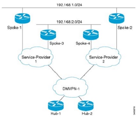
Note: The command "no next-hop-self" means that the router will not put it's own ip-address in the next-hop field when advertising routes. The added parameter "no ecmp-mode" means that the router will evaluate every route in the EIGRP topology and advertise those out that interface.
As I was trying to explain before, this is an extremely rare situation where you would have to basically have a simular topology to the above and multiple tunnel-interfaces receiving the same routes so that your HUB-router is doing ECMP towards a network. That network is learned through multiple paths downstreams, and you need to advertise both paths downstream - that's the case and situation where you run into this problem.
Time Required: 5 hours.
daniel.larsson- Admin
- Posts : 47
Join date : 2015-04-30
Age : 41
Location : Boras, Sweden -
Layer 3 - Open Shortest Path First PART 1
![]() by daniel.larsson Wed Jul 08, 2015 11:55 am
by daniel.larsson Wed Jul 08, 2015 11:55 am
Technology
- OSPF
- OSPF Initialization
- OSPF Network Statement
- OSPF Interface Statement
Open Shortest Path First PART 1
(OSPF, OSPF Initialization, OSPF Network Statement, OSPF Interface Statement)
Notes Before reading: The first few topics of OSPF are extremely technical and difficult to grasp when you take them apart so the number of hours spent with labs and theory will be shown after the last OSPF LSA-type since i split them into a single study-session rather than studying them as a single session.
That means that I did not keep track of the individual amount of time required for each part below, however i did keep track of all the time required to complete ALL the topics from the CCIE RSv5 Blueprints that can be considered "common" OSPF-knowledge.
This section starts some very difficult topics to grasp with many new topics that were previously not part of either CCNA or CCNP. Overall this section is almost as big as the BGP-section and combined I estimate the OSPF-section to take as much time as EIGRP and RIPv2 combined.
Mainly because OSPF is a very complex protocol and a very difficult one to master. Even if I consider myself very skilled at OSPF I think I will run into many situations here that are new. Many of the new topics are considered network optimization topics that requires a solid understanding of how OSPF actually work behind the scenes before going into that area.
That means that I will have to cover OSPF from the bottom basics up to the top to get a CCIE-level of understanding. Many of these topics also overlaps with CCNA and CCNP, but not in the depth that is required for CCIE so even if it helps to have the foundation level experience from CCNA/CCNP it is not enough for the core/foundation level of OSPF.
As far as the INE videos for OSPF goes, they cover OSPF in very much depth with over 20 videos for just the OSPF IPv4 parts! That's about the same amount of videos for EIGRP and RIPv2 combined! So that by itself confirms that this is a deep topic!
And the labs are also comprehensive when it comes to OSPF, covering over 250 pages in total with everything from the bottom to the top in there. That makes sense, from my personal work experience many engineers truly don't understand how OSPF works, so it makes sense to cover OSPF in depth before moving on to BGP.
Given the complexity of OSPF I will naturally divide these topics into more reasonable parts, I am not sure yet but it's going to be much more parts than previously. OSPF is just such a complex and advanced protocol that it's difficult to create a study plan for it. As soon as you start to think you understand the concept, you discover that you didn't and have to restudy other parts.
But I will cover all the topics in depth with a strong focus on grouping together the parts to start with the basics and move up. I just don't know a good way to group this protocol, so i will try and cover the basics up to the top at a CCIE-level of understanding and divide it into parts along the way. From previous experiences with OSPF, I know that this will be a long studyguide/many study notes.
PART 1 - Introduction to OSPF and some basic information how it works.
OSPF, OSPF Initialization, OSPF Network Statement, OSPF Interface Statement
I would say that these are all topics that are covered by CCNP R&S. But they are not covered in a CCIE-depth of understanding. So i will make sure to cover them from the basics and up either way just to make this a CCIE-level of studying. And as usual when it comes to the core concepts and foundation understanding, there is no better book than the CCNP ROUTE by Wendel Odom.
As with EIGRP PART 1, for all these topics only a single book is required. Since it's written by Wendel Odom it's extremely technical and very accurate. The problem is they don't cover the more advanced problems with OSPF since they don't exist outside the scope of CCIE. For example it does not cover Type 4, 5, 7 LSA's in depth or very well. But it's a good starting point:
Book: CCNP ROUTE Official Certification Guide, Chapter 5-6.
Chapter 5 is named: OSPF Overview and Neighbor Relationships.
Chapter 6 is named: OSPF Topology, Routes and Convergence.
Since it only covers some part of the OSPF-technologies in the blueprint, i will also have to look at the official Certification Guide:
Book: CCIE RSv5 Official Certification Guide, Chapter 9.
Chapter 8 is named: OSPF.
IP Routing - OSPF Configuration Guide Link: http://www.cisco.com/c/en/us/td/docs/ios-xml/ios/iproute_ospf/configuration/15-mt/iro-15-mt-book.html
Note: There is just so, so much to read about OSPF so there's no good and accurate configuration guides to point towards. Since almost every single topic of OSPF has it's own configuration guide, like LSA 1, LSA2, LSA3 etc. Therefor the link to all the configuration guides seems like the best one to use.
Learned:
-That there's too much information about OSPF to actually be able to learn any topics from the configuration guides. However they're well worth a read-through to see how Cisco implements OSPF compared to the RFC-standard. Which we will see - they make a few changes along the way.
OSPF (a short overview of OSPF concepts and how it works)
-OSPF is a very complex so called Link-State routing-protocol. That means that every router in the topology will maintain a Link-State database containing detailed information about the state of the network topology.
When you first look at OSPF it doesn't look too complex, and in a small-to-medium sized network there is not much problems you can run into when using OSPF. It's not until you scale it to a more Large network when the complexity of OSPF will show it's true nature of operations.
Since this is a small overview of what OSPF is, i will not go into the details more specifically. However it's worth meantioning that OSPF mainly does three things as a routing-protocol. These things are:
- The neighbor discovery process.
- The topology database exchange process.
- The route computation process.
In short it means that when compared to EIGRP, you can see that it's a more complex protocol because it has three major parts. EIGRP only uses the neighbor discovery and the route computation/route exchange process.
A very brief explanation of the above processes will follow before going more into detail of each one later on:
The neighbor discovery process
-Pretty much using the same logic as EIGRP. The end goal of this process is to find neighbors and be able to make a decision about whether the local router should exchange routing-information with eachother.
The logic is almost the same as with EIGRP since OSPF also uses a neighbor-database to keep track of all it's neighbors. There are a lot of different things that needs to match with OSPF to form a neighbor adjacency, but more on that later.
The topology database exchange process
-This step is what makes OSPF a Link-State protocol. This process end goal is to exchange enough information with neighboring routers so that every router in the topology can draw their own topology map. The goal here is to learn topology information from each neighbor in the topology and store this information in the local topology database.
The local topology database is called the LSB-database (LinkStateDatabase). Not to go into too much detail of what this stores, but it stores enough information to draw a map to each and every individual link in the entire OSPF topology. To do this, some of the information that is stored is the following:
- -Some way to identify each router in the topology (the Router-ID)
- -Every router interface, it's ip address and it's subnetmask.
- -A list of every router that is reachable on each interface.
As can easily be told by the above information, it means that every local OSPF router knows how to reach every other router in the topology over every single link! That's why it's called the Link-State Database and a Link-State routing-protocol.
The route computation process
-Every router will compute the best way to reach a specific route by calculating the way towards that route based ENTIRELY on it's own Link-State database! In other words, OSPF runs the so called SPF-algorithm for every reachable subnet within the OSPF topology and then chooses the shortest path from it's own perspective based on the information in the topology database!
Notice the difference here, it uses it's OWN local database to compute the routes. This means that it's unimportant how a router several hops away routes it's traffic because every OSPF-router will have their own OSPF topology in their database. So they will calculate a path towards the route entirely on their own.
Then after that normal procedure goes on to select the next-hop address and the next-hop outgoing interface for each subnet. If the OSPF-route for that specific subnet happens to be the best path, and have the lowest Administrative Distance it will be added to the routing-table by the router.
Design Note: It doesn't matter at all whether or not the router will actually install the routes in the routing-table, every single OSPF-router will still have to calculate the best path to reach every single subnet that is reachable within the OSPF-topology... REGARDLESS of whether or not the route will actually be used by the router!
Therefore, OSPF is considered to be a resource-demanding routing-protocol that takes a lot more CPU and memory than a Distance Vector routing-protocol. But more on that later on!
But since OSPF is a Link-State routing-protocol you also have to tell the OSPF-process where in the topology all these link-states will belong. That's where you tell the OSPF-process which Area to install the Link-States into.
A brief explanation about OSPF-areas needs to be done before moving on with the configuration.
EIGRP uses a topology database, which is much less complex than the OSPF-databse. OSPF needs to keep track of every single link in the entire OSPF-topology. Not only does it require to keep track of all the links, it must also compute every single subnet that is reachable. Each subnet can be reachable out different sub-domains within the OSPF-topology. These sub-domains are called Areas.
For OSPF to work, there must be a backbone area or the Area 0. In area 0 every single route must be known to each and every router that is part of the backbone area. This also means that it's called the backbone area for a reason, since EVERY other area connection will flow through the backbone Area 0.
The concept to understand here is that every router in the backbone/core will know about every other area in the topology. Every router in a sub-domain (routers belonging to different area than 0) does only need to know about every router inside that sub-topology AND a route to reach area 0 (the backbone).
This design is hierarchical, meaning that traffic will flow in a very predetermined path. And every router in OSPF needs to be able to calculate the path. As such, every sub-area must be connected somewhere to the backbone Area 0.
Two sub-areas can not be directly connected to each other, since the topology is hierarchical it means that the traffic must flow through Area 0 between two sub-areas. This has to do with how OSPF works and the SPF-algorithm calculates the best route/path to subnets! But more on that later on.
But as we will see later on, the RFC-standard and the Cisco implementation of OSPF deviate from eachother for this scenario.
Design Note: For a well designed OSPF-network, a considerably amount of time needs to be invested to design OSPF-areas in such a way that the complexity of the network does not steal too much resources of the connected routers in each sub-area.
From a design perspective, this also means that the best routers should be placed in Area 0. And the routers with less resources should be placed in sub-areas.
But to better understand the OSPF-concept, a network topology example is required:

In this design R1 and R2 are part of multiple areas, they are the backbone areas. R3 and R5 are only part of a single sub-area. The area 10 and area 20 are connected to the backbone Area 0. R4 is to demonstrate a different concept of what happens when a router connects two sub-areas with each other. That is a later concept, so for now just look at Area 10 and Area 20.
This design is to keep changes in Area 10 from affecting the routers in Area 20. That's why you would normally see multiple OSPF-areas in a design. However changes that happens in both Area 10 and Area 20 will still affect the routers in Area 0.
The point I want to demonstrate here is that OSPF are very hierarchical. Meaning that for R5 to speak with R3 the traffic would need to flow through R2 and R1. You "can't" route traffic from R5->R4->R3 even though that path looks "shorter". Because that traffic don't flow through the backbone area.
Without going into the details, for now just learn that R5 and R3 only knows how to reach Area 0 and subnets within it's own sub-area. In other words, R3 knows how to reach subnets in Area 10 and how to reach area 0. R5 knows how to reach subnets in Area 20 and how to reach area 0.
Area 0 will know about every route to every subnet in the OSPF-topology. So the idea is that by keeping OSPF hierarchical you can segment and create sub-areas for your OSPF-topology to reduce the router resources required to run OSPF.
Note: The reason that the Area 0/The backbone area knows about every other subnet is because you are not allowed to supress information advertised into this area by making this area a special area type that limits information learned. We will see more of that later on!
That sums up the basics of what OSPF is and how it in general work and what the design goals with OSPF are. So let's move onto some OSPF concepts and configurations!
OSPF Initialization
-Compared to EIGRP OSPF requires more thought when enabling the process. However it's pretty simple to turn OSPF on and enable it on every interface. It can be done with a single command.
(more about that later but for reference: network 0.0.0.0 255.255.255.255 area 0)
With OSPF there are no such thing as Named-Mode, you just configure it like Classic EIGRP using the following command:
router ospf <process id>
network <network address> <wildcard mask> <which area the interface belongs to>
However there is also a specific interface-command that lets you configure OSPF directly under an interface. The command is simular to the global process:
configure terminal
interface fa0/0
ip ospf <process id> area <which area the interface belongs to>
From a configuration perspective it makes no difference at all how you choose to configure OSPF, it will work the same.
But from a learning-perspective, it's probably going to be better to use the interface command since that will prepare you better for the IPv6 configuration which is mostly done in interface-configuration mode. And also since OSPF is a Link-State routing protocol and it keeps track of the links. So it makes sense to configure the OSPF process on the link itself.
So now we know how to turn OSPF on, but before moving on to a topology configuration example, we need to know what exactly happens when we turn the OSPF-process on.
OSPF Network Statement, OSPF Interface Statement
When the interface is matched with a network-statement the following will happen on that interface:
- It attempts to discover OSPF neighbors on that interface by sending multicast OSPF Hello-messages. The multicast-address is 224.0.0.5, which means "all OSPF-routers".
Note: As we will learn later on, there are different OSPF-addresses for different purposes where the majority of the OSPF-updates will go to address 224.0.0.6 which is "all DR/BDR routers". - It will include the connected subnet in the future topology database exchanges to be made.
Let's assume that the OSPF-interface we just enabled actually finds another OSPF-router out that link. It will then start the process to decide if they should start exchanging topology information. To do so a lot of parameters in general have to match for OSPF routers to become neighbors. - If the two routers agrees on every parameter needed to be able to exchange topology information, the two routers will start the exchange-process. This process by itself is so complicated that it requires a thorough understanding of OSPF to even discuss it.
Basically it will work differently depending on which network-type is used, the end goal will be to select who will be the master or the slave (in other words, who will send their updates first) on the link and also to determine the role of the router (more on that later). - Once the routers agreed to the parameters, and exhanged their topology information the routers will keep the neighbor relationship by periodically checking if the other neighbor is still alive. The so called hello-timer sends information to the remote-neighbor that it's still active. The dead-timer is a counter that resets everytime a hello-packet is received from a remote router.
This process by itself is how OSPF determines if routers are considered Down or not. If the dead-timer expires, the neighborship with that router is terminated. Of course OSPF, like EIGRP, uses triggered updates to update information directly when they happen so it doesn't have to wait for the Dead-timer to expire. The dead-timer is for those rare situations where the router does not receive information about a link-state that should inform it about a lost link to a remote-router.
Important Study Note: All these topics requires a solid understanding and a deeper explanation by themselves. For the first two parts, they are covered in this part of my studynotes. The 3rd and 4th topics are covered later on after learning about the different network types.
But it's very important to understand that enabling the OSPF process will start a topology exchange if all parameters match, and continue to keep track of neighbors reachability using hello and dead timers! (simular to Distance Vector protocols)
So let's move on to:
Which parameters OSPF will check to determine if they should become neighbors?
OSPF is extremely picky when it comes to selecting candidate routers to exchange OSPF topology information with. As such the following are all the parameters that MUST MATCH before two OSPF routers will become neighbors:
- The OSPF primary interfaces IP-addresses must belong to the same Subnet.
- The OSPF primary interfaces IP-addresses must also use exactly the same subn-etmask.
Note: It's possible to configure a network so that the wildcard match will belong to the same subnet but with different subnet-masks. Unlike EIGRP, with OSPF the subnetmask must be 100% identical. - Both interfaces must belong to the same OSPF Area.
- Both the Hello Interval/Timer and the Dead-timer of OSPF must match.
- The Router ID's must be unique.
- The IP MTU must match.
Note: Even if the MTU is a mismatch, the routers may be listed as OSPF-neighbors but they will not exchange topology information! - Authentication parameters must match.
- No interfaces may be configured as a passive-interface.
- The stub-area flag must match.
Those are a lot of parameters, however in most scenarios these are the basic parameters that in general OSPF compares:
- -The router ID.
- -The subnet mask.
- -The area type (more on that later on).
- -The hello and dead intervals.
Note: Compared to EIGRP it is not required that the OSPF process ID's be a match, they are not exchanged in the OSPF hello-messages.
This can be further demonstrated by looking at how the OSPF packet look like:

As you can see in this picture all the above information is listed in the OSPF Hello Packet.
It will not matter if you turn on the OSPF-process under the global OSPF-process or under a specific interface. It will work just the same. But to better understand a configuration example, lets use the same topology as before.
So to demonstrate how to configure the following topology:
To configure this under the global process:
!R1
router ospf 1
network 10.0.0.0 0.0.0.255 area 0
network 192.168.10.0 0.0.0.255 area 10
!R2
network 10.0.0.0 0.0.0.255 area 0
network 192.168.20.0 0.0.0.255 area 29
!R3
network 192.168.10.0 0.0.0.255 area 10
!R5
network 192.168.20.0 0.0.0.255 area 20
To configure this under each interface:
!R1
configure terminal
interface fa0/0
ip ospf 1 area 0
interface fa0/1
ip ospf 1 area 10
!R2
configure terminal
interface fa0/0
ip ospf 1 area 0
interface fa0/1
ip ospf 1 area 20
!R3
configure terminal
interface fa0/0
ip ospf 1 area 10
!R5
configure terminal
interface fa0/0
ip ospf 1 area 20
The network statement here does the same thing as with EIGRP. The end goal is to start the OSPF-process on those interfaces and try to discover OSPF-neighbors to exchange topology information with.
There is much more to this command when it comes to OSPF, but all these more complex things will be covered individually on later sections. But they must still be meantioned here because they are part of the network command.
For example the network command will start:
- -to send OSPF-hello messages to multicast address 224.0.0.5
- -when neighbors are formed, start the exchange process which by itself is a very complex and difficult topic to grasp.
- -decide which network-type it's connected to and whether or not it should select a Designated Router and a Backup Designated Router.
- -decide which hello and dead timers to use by default. All which must be a match with the remote-neighbor!
So to further continue our introduction to OSPF, we must dig into the different OSPF Network types that are available before we can proceed to explain the exchange-process in more depth.
Last edited by daniel.larsson on Mon Jul 27, 2015 9:54 am; edited 1 time in total
daniel.larsson- Admin
- Posts : 47
Join date : 2015-04-30
Age : 41
Location : Boras, Sweden -
Layer 3 - Open Shortest Path First PART 2
![]() by daniel.larsson Fri Jul 10, 2015 2:22 pm
by daniel.larsson Fri Jul 10, 2015 2:22 pm
Technology
- OSPF Network Types
- OSPF Broadcast
- OSPF Non-Broadcast
- OSPF Point-to-Point
- OSPF Point-to-Multipoint
- OSPF Point-to-Multipoint Non-Broadcast
- OSPF Loopback
Open Shortest Path First PART 2
(OSPF Network Types, OSPF Broadcast, OSPF Non-Broadcast, OSPF Point-to-Point, OSPF Point-to-Multipoint, OSPF Point-to-Multipoint Non-Broadcast, OSPF Loopback)
Notes Before Reading: This section covers introduction to some very complex scenarios and topics of OSPF. We are still not technically speaking discussing OSPF from a CCIE-level of perspective but some of the topics covered in this part is extremely important to OSPF, but still considered to be basic OSPF operations.
All of these topics are actually covered in CCNA/CCNP but obviously not at the depth required for CCIE-studies. Overall you will do very well with just CCNA/CCNP books on this section but that will depend on how well your foundation level of understanding OSPF is. Meaning, these topics are extremely important to OSPF and they are very difficult to explain - and it will be the foundation to dig deeper into OSPF to truly understand how it works.
OSPF is a very complex protocol and a very difficult one to master. Even if I consider myself very skilled at OSPF I think I will run into many situations here that are new. Many of the new topics are considered network optimization topics that requires a solid understanding of how OSPF actually work behind the scenes before going into that area.
OSPF Network Types, OSPF Broadcast, OSPF Non-Broadcast, OSPF Point-to-Point, OSPF Point-to-Multipoint, OSPF Point-to-Multipoint Non-Broadcast, OSPF Loopback
All these topics are covered by CCNP R&S. But they are not covered in a CCIE-depth of understanding. So i will make sure to cover them from the basics and up either way just to make this a CCIE-level of studying. And as usual when it comes to the core concepts and foundation understanding, there is no better book than the CCNP ROUTE by Wendel Odom.
As with OSPF PART 1, for all these topics only a single book is required. Since it's written by Wendel Odom it's extremely technical and very accurate. The problem is they don't cover the more advanced problems with OSPF since they don't exist outside the scope of CCIE. For example it does not cover Type 4, 5, 7 LSA's in depth or very well. But it's a good starting Point.
For this specific part of the studies, the CCNP ROUTE book is a really good source. But what it doesn't cover is the details of how things work behind the scenes, but since I'm keeping this to an introduction sort of studies - it's not required to be extremely in depth of how it works. It will be covered in later sections when it's needed to know how it works before moving on.
Book: CCNP ROUTE Official Certification Guide, Chapter 5-6
Chapter 5 is named: OSPF Overview and Neighbor Relationships.
Chapter 6 is named: OSPF Topology, Routes and Convergence.
Since it only covers some part of the OSPF-technologies in the blueprint, i will also have to look at the official Certification Guide:
Book: CCIE RSv5 Official Certification Guide, Chapter 9.
Chapter 8 is named: OSPF.
IP Routing - OSPF Configuration Guide Link: http://www.cisco.com/c/en/us/td/docs/ios-xml/ios/iproute_ospf/configuration/15-mt/iro-15-mt-book.html
Note: There is just so, so much to read about OSPF so there's no good and accurate configuration guides to point towards. Since almost every single topic of OSPF has it's own configuration guide, like LSA 1, LSA2, LSA3 etc.
Learned:
-That there's too much information about OSPF to actually be able to learn any topics from the configuration guides. However they're well worth a read-through to see how Cisco implements OSPF compared to the RFC-standard. Which we will see - they make a few changes along the way.
OSPF Network Types, OSPF Broadcast, OSPF Non-Broadcast, OSPF Point-to-Point, OSPF Point-to-Multipoint, OSPF Point-to-Multipoint Non-Broadcast, OSPF Loopback
-OSPF uses the concept of "OSPF Network Types" to determine how it should work in the background. The network type will mainly decide three things:
- -If the OSPF-process should elect a Designated Rotuer and a Backup Designated router.
- -Which OSPF-timers the OSPF-process should use by default.
- -If the OSPF-process will be able to dynamically discover neighbors or if you have to statically define the neighbors manually under the OSPF-process configuration.
Design Note: In other words, the network type decides whether or not that interface will support Multicast. No multicast support means that you have to statically configure neighbors on that link.
There is a lot more to OSPF than there ever is to EIGRP or RIPv2 when it comes to what happens when you enable the routing-protocol on a link.
What I mean by that is that there are mainly two major different types of network that OSPF uses:
- -The Broadcast network type. (Cisco proprietary implementation/Not RFC Based)
- -The Non-Broadcast network type. (RFC-based implementation)
The difference between these two are again mainly three things:
- -The first thing is for OSPF to decide if there should be a DR/BDR election on that link.
- -The second thing it does is tell OSPF what default timers to use on that link when trying to form neighbor relationships.
- -And the last thing it does is to either discover neighbors using multicast address 224.0.0.5, or disabling multicast on that interface.
To complicate it even more, on top of that there are three other minor "Network-types that OSPF uses". I put them around a quote because it's easier explained if you use the terminology "link-types". They will fall into either Broadcast or Non-broadcast categories.
Per OSPF-terminology these are also Network-Types, but I prefer to refer to them as Link-Types:
- Point-to-multipoint (Broadcast, RFC-based implementation)
- Point-to-multipoint nonbroadcast (Nonbroadcast, Cisco proprietary implementation/Not RFC Based)
- Point-to-point (Nonbroadcast, Cisco-proprietary implementation/Not RFC Based)
- Loopback-interfaces (included in the blueprint but it will only be available on loopback interfaces by default)
Note: They are actually considered OSPF-network types, however they either support broadcast or they don't. So it's much easier to learn if you understand that there are in total 5 different OSPF-network types, but only two major ones. The minor ones are when using Point-to-Point links and they will be either Broadcast or Non-broadcast links.
The Point-to-Point links are going to be working in either Broadcast or Nonbroadcast mode and that's why I find it so much easier to refer to them as "the link-type". The reason is that because when running Ethernet, it will be a broadcast medium. When running sub-interfaces, it will in general be a point-to-point link that either supports or doesn't support multicast.
The nonbroadcast networks are in general legacy networks such as Frame-Relay, X.25 and so on - that simply put doesn't use Ethernet and therefor doesn't support broadcast. When creating sub-interfaces they can either belong to a network that supports ethernet (multicast/broadcast supported) or to a network that is not Ethernet based (doesn't support multicast/broadcast).
The key thing to really understand is that the connected network type doesn't have to be Ethernet, it could be anything. And OSPF will work differently depending on the network type it's connected to!
So I will divide the next topics and group them under the same network-type so it's easy to see which Link-Types do belong to which Network-Type.
It makes no sense to study them without knowing which network-type they belong to, as the network-type is much more important than the link-type is.
But before going into that we need to understand what a Designated Router is and what the Backup Designated Router is. And that is not an easy topic to dig into.
Designated Routers and Backup Designated Routers. What is it?
The best way I can explain it is that within OSPF there are some optimization techniques that you can use to tune the protocol to be less resource intensive. But OSPF has a built-in feature that tries to solve this problem for you.
What it really does behind the scenes is that it's responsible for the so called "Type 2 LSA's" on that segment. Even if we haven't talked about LSA's yet it's important to understand that OSPF requires that neighbors exchange topology information with eachother.
In OSPF terminology that means to exchange the database/LSDB. The problem is that to map the network, OSPF requires two routers to directly exchange their Link-State information with eachother. In easier terminology, it means that OSPF needs to be directly connected to the other router on that link.
But on a shared segment, it can be connected to multiple routers.
How would OSPF be able to build a topology like that?
OSPF will choose one router to to create a so called Type 2 LSA. From the OSPF point of view it will look like it's connected directly to the router that created the Type 2 LSA. On a shared segment that will be the Designated and the Backup Designated Router. They are responsible for advertising and creating the Type 2 LSA's so the other routers on that segment will exchange topology information directly with them.
Note: All links are represented by a so called Type 1 LSA which tells other routers about their connected links. What the DR/BDR does is that it creates a Type 2 LSA for the shared subnet. And all other routers that are not DR/BDR on that segment will create a Type 1 LSA for all their links and map this to the Type 2 LSA from the DR/BDR. This means that from the other routers it will look like they have a point-to-point link with the DR/BDR. That solves the problem that the routers are connected to a shared segment.
We haven't touched these topics yet, but OSPF uses the concept of so called Link-State Advertisements to flood information about links within the OSPF-topology. If every router would use the multicast address 224.0.0.5 every router would need to know about all these Link-State Advertisements.
In a small OSPF network that is not a problem, but when we talk about large-scale OSPF networks - that will become a major network issue since when a link goes down, that router advertises about that link-state inside the entire OSPF-domain. Every router that receives this LSA would have to rerun the SPF-algorithm to reconverge to have the complete map of the topology.
The SPF-recomputation will always have to be made since it's a Link-State protocol. But what the DR/BDR will try to solve for you in a larger network is that it makes no sense to send these advertisements out to every single router in your network, instead let's send these advertisements to a Designated Router and a Backup Designated Router.
The DR and the BDR will then be the only two routers on that segment of the network to be receiving these Link-State advertisements from other routers. So every router on that segment will instead use the multicast address 224.0.0.6 which means "all OSPF DR and BDR routers" to send their updates towards.
When there is a change in the topology the DR and the BDR is then directly responsible to propagate these changes to the affected routers. They do this by informing the affected routers based on their on Link-State Database.
For now let's not go into detail how exactly the DR/BDR works, at this point it's only required to know that the Network-type will decide whether or not to use a DR/BDR. To summarize this section let's look at a topology example with a single area:
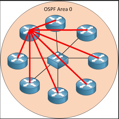
This is not a complicated topology, and without explaining why - all these routers are connected to the switch in the middle. So there will be a DR/BDR election process since Ethernet is considered a shared broadcast network type.
In this case the router in the top-left corner have all the red lines going towards it, it did win the DR election process. So now every other router connected to that segment is sending their Link-State Advertisements towards this router instead of flooding the entire network segment with these updates.
What happens then is that whichever router is the DR/BDR will have a complete Link-State-information on that segment, the other routers knows how to reach the DR/BDR routers.
The DR/BDR will then keep the other non DR/BDR routers on that segment updated when there is a Link-State change that they need to be informed about. The design goal with DR/BDR is that instead of making every router learn about all the Link-State information, concentrate this to two routers with more resources and let them do the dirty work.
This is one of the optimization processes that OSPF-uses to try and overcome the fact that the SPF-algorithm takes a lot of CPU-resources whenever there is a Link-State change in the network.
Note: This is just briefly explained and is not the full concept of how it works, but for now it's what you need to know to move on to the various Link-Types and Network-types. The most important thing to remember is that the DR/BDR will do more SPF-calculations than the routers that are not DR/BDR.
A full detailed overview with how the OSPF-process sends and updates various LSA's will be covered in the section where we discuss why DR/BDR election manipulation can be important.
The purpose of OSPF Network Types
-I did meantion that the idea with the OSPF Network-Types are to decide whether or not to use the DR/BDR concept. That requires some more explanation.
Included in the process when OSPF discovers which Network Type it's connected to are three major decisions OSPF does. It will define how OSPF will work in your network:
- 1. When you enable OSPF on a link it will decide whether or not that link is considered to be part of a Broadcast-network or a Non-Broadcast network.
What this really does is that it ultimately decides if the OSPF-process should start the DR/BDR election process on that link. That is the purpose of the Broadcast vs Nonbroadcast network types.
- 2. What it also decides is whether or not to use multicast on that link or not.
For OSPF that means:
-If it decides to use multicast - neighbors will be dynamically learned on that link.
-If it decides to not use multicast - neighbors must be manually configured to form a relationship.
- 3. Each network-type (broadcast and non-broadcast) also have multiple types of links to chose from. The link-types I'm talking about is the Point-to-point options. To review they are:
-Point-to-Multipoint
-Point-to-Multipoint nonbroadcast
-Point-to-Point
-Loopback
The purpose of what I want to call "Link-Types" (but it's really a Network Type per OSPF definition) is that you will have the option to tell how OSPF will behave on that link. With that I mean that:
-The Link-Type will decide whether or not a BD/BDR election process will start on that link and if it will support multicast (to discover neighbors dynamically) or if it doesn't support multicast (to manually configure static neighbors on that link).
Note: More accurate from a technical viewpoint, it will decide if that link should participate in a BD/BDR election process. Since the network type needs to be a match for OSPF adjacencies, both ends must agree to the election process but it doesn't per definition say that a DR/BDR election is to be made. It strictly tells the OSPF-process to either participate or don't participate in the DR/BDR election process on that link.
From my own experience, I believe that this is the most difficult topic to understand when dealing with OSPF-type of networks. Due to the many number of different combinations to choose from, it's difficult to try and memorize all the different scenarios.
To understand OSPF you must also know the different timers that are used by default on the various network-types. Because in OSPF all the timers have to be a match or neighbors will not be able to form a relationship with each other.
Important design and study note: From this section it's important to understand that the network type Broadcast vs Nonbroadcast will decide if you must manually configure neighbors (Nonbroadcast type) or if neighbors can be dynamically learned (Broadcast network type) and which default timers it will use for OSPF.
Important Study Note 2: I have not covered the BD/BDR election for Broadcast and Nonbroadcast networks, but it will be covered in detail in a later section!
So let's move on to the three minor network-types that OSPF can use.
- -OSPF Point-to-Point
- -OSPF Point-to-Multipoint
- -OSPF Point-to-Multipoint Non-Broadcast
- -OSPF Loopback
I consider these to be the minor network types, as you will most likely only come across them when dealing with Sub-interfaces which is typically created for Point-to-Point links of some sort. But of course the Point-to-Point links will be also be represented by various WAN-connections and interfaces such as Serial-interfaces etc.
When using OSPF they will all work somewhat differently:
- -They will all be considered to either support Broadcast/Multicast or to not support it - which means whether or not OSPF will be able to dynamically form relationships with other routers or not.
- -They will also decide whether or not to participate in the DR/BDR election on that network segment.
To further complicate these topics, some are considered RFC-standards and other types are considered to be a Cisco Proprietary implementation.
That is important to know because from a CCIE-Lab point of view you may be required to implement OSPF in such a way that it complies with RFC-standards, in that case you only have two viable opitions to choose from - Nonbroadcast or Point-to-multipoint.
But there is more to that - let's look at the OSPF-packet format again:
Notice that there is absolutely no information at all that is included to learn what network-type the remote neighbor is using. However every other field is still represented in the hello-packet.
Very important note: This means that you can have an OSPF-network type mismatch and still be able to form a neighbor relationship as long as the other parameters are a match.
From a Lab-point of view this can be a very tricky situation where they might end up telling you to configure a OSPF Broadcast link in one direction to link up with a Point-to-Multipoint nonbroadcast in the other end. By default these will not work due to timer-mismatches and multicast vs no multicast support, but with tweaks and manipulation of OSPF timers and OSPF neighbors you can run two different network-types.
Important study note: What matters in the end is whether or not the OSPF-parameters that are checked before forming a neighborship will match or not. Make them the same and they will form a relationship assuming that they can speak to each other.
I cannot express how important the different network types are to understand how OSPF will operate. Even if I haven't summarized the BD/BDR election process it's still a very important fact to remember about OSPF Network-types, whether or not there will be a BD/BDR election on that segment.
So to easier remember, let's summarize the different network-types and how they will operate by default:
OSPF Broadcast
This network type is considered to be a Cisco-proprietary network-type since it's not RFC-based. This means that only cisco-routers will support this network-type. The summary for Broadcast networks are:
- -They support broadcast/multicast, so neighbors will form dynamically.
- -Default hello timer is: 10 seconds.
- -Default dead timer is: 40 seconds.
- -DR/BDR will be elected.
OSPF Non-Broadcast
This network type is considered to be multi-vendor supported since it's RFC-based. The summary for Nonbroadcast networks are:
- -They don't support broadcast/multicast, so neighbors will not form dynamically.
- -Default hello timer is: 30 seconds.
- -Default dead timer is: 120 seconds.
- -DR/BDR will be elected.
OSPF Point-to-Point
This network type is considered to be a Cisco-proprietary network-type since it's not RFC-based. This means that only cisco-routers will support this network-type. The summary for Point-to-Point networks are:
- -They support broadcast/multicast, so neighbors will form dynamically.
- -Default hello timer is: 10 seconds.
- -Default dead timer is: 40 seconds.
- -No DR/BDR will be elected.
OSPF Point-to-Multipoint
This network type is considered to be multi-vendor supported since it's RFC-based. The summary for Point-to-Multipoint networks are:
- -They support broadcast/multicast, so neighbors will form dynamically.
- -Default hello timer is: 30 seconds.
- -Default dead timer is: 120 seconds.
- -No DR/BDR will be elected.
OSPF Point-to-Multipoint Non-Broadcast
This network type is considered to be a Cisco-proprietary network-type since it's not RFC-based. This means that only cisco-routers will support this network-type. The summary for Point-to-Multipoint nonbroadcast networks are:
- -They don't support broadcast/multicast, so neighbors will not form dynamically.
- -Default hello timer is: 30 seconds.
- -Default dead timer is: 120 seconds.
- -No DR/BDR will be elected.
OSPF Loopback
This is a very special case which will only affect loopback interfaces. There is a OSPF network type called "loopback" which means that the network attached to that interface belongs to a loopback interface.
By default this means that the OSPF process will treat this link as a host-route, so it will automagically advertise this network to other routers as a "host-route" with a /32 mask attached to it.
Normally you would never have to change this, and loopback interfaces can't form any neighborships with other OSPF-routers so there are no concept of Broadcast vs Nonbroadcast or DR/BDR election on this interface.
But the important thing to understand is that if you capture a packet and look how this network is treated, it will be a "stub host" type of link, which means it should be advertised as a "host route with a /32 mask" to other routers.
To manually tune this you can go into the interface and change it with this command:
router ospf 1
network 0.0.0.0 255.255.255.255 area 0
exit
interface loopback0
ip address 192.168.1.1 255.255.255.0
ip ospf network point-to-point (or whatever you want it to be)
By doing that you change that link from a "loopback" network type into whatever you configure it to be, and by doing that the complete subnetmask will be advertised to other OSPF-routers.
Note: Normally you would never need to change this except for in lab-environments where you want to simulate a lot of other networks behind a specific router. To stop it from advertising host-routes you would need to manually change the network-type into something OSPF in general uses to advertise the actual subnetmask.
All OSPF Network Types summarized with a study comment
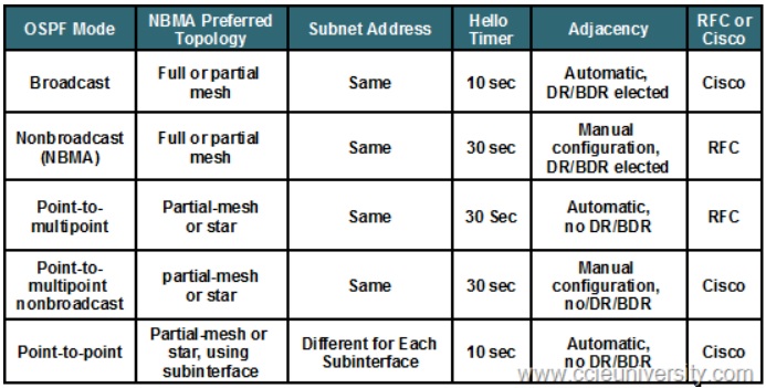
Note: As can be seen by the image summarized above it's easier to remember the OSPF default operations using this technique:
- -If the link is a special Point-to-Point link of any sort, no DR/BDR will be elected.
- -If the link is a Nonbroadcast of any sort, it will not support multicast/broadcast so neighbors will not be learned dynamically.
Note: Of course there is Cisco's implementation of a Point-to-Point link called simply "Point-to-Point" where there is no DR/BDR but it still supports Multicast for dynamic neighbor discovery.
That's really the only thing you need to remember about this complicated topic.
Change the OSPF network type on a link:
-It may be required to change the OSPF network-type on a link, it's easily done under interface configuration. So let's say we want to change the link type all you would have to do is go into the interface and type:
ip ospf network type broadcast
ip ospf network type non-broadcast
ip ospf network type point-to-multipoint
ip ospf network type point-to-point
Note: That will change the network-type on that link into what you configure it for. This is one of the tools you have available for manipulating OSPF during the lab. You may be required to make a link between two OSPF-routers to form adjacency without modifying any OSPF-timers, then you can modify the network type so it will change the timers until there is a match so adjacencies can be formed.
Since this is not advertised in the OSPF Hello-packet, you are just manipulating how OSPF behaves on that interface/link with the above commands.
Verification note: There is not much to this section, but to verify the network type of OSPF you can use the following command:
show ip interfaces ospf <interface name>
And you will see all of the details about an interface. An example output for my loopback0 interface:

daniel.larsson- Admin
- Posts : 47
Join date : 2015-04-30
Age : 41
Location : Boras, Sweden -
Layer 3 - Open Shortest Path First PART 3
![]() by daniel.larsson Mon Jul 20, 2015 10:33 pm
by daniel.larsson Mon Jul 20, 2015 10:33 pm
Technology
- OSPF LSA Types
Open Shortest Path First PART 3
(OSPF LSA Types)
Notes Before reading: This section is a very short introduction to some of the advanced and complex parts of OSPF, but not in a very deep understanding. This section is going to be a foundation introduction to OSPF-concepts about LSA-types.
We will just cover the top of the ocean before moving into the LSA-types. The reason I keep this a very short section is becuase I felt the need to explain what LSA-types are before going into a discussion about how each one of them will work in a complex network.
Again all of these topics are covered in CCNA/CCNP but obviously not at the depth required for CCIE-studies. Overall you will do very well with just CCNA/CCNP books on this section.
I've said it before but I will repeat myself.
OSPF is a very complex protocol and a very difficult one to master. Even if I consider myself very skilled at OSPF I think I will run into many situations here that are new. Many of the new topics are considered network optimization topics that requires a solid understanding of how OSPF actually work behind the scenes before going into that area.
OSPF LSA Types (and the Link-State advertisement process)
This topic are covered by CCNP R&S. But it's not covered in a CCIE-depth of understanding. So i will make sure to cover it from the basics and up either way just to make this a CCIE-level of studying. And as usual when it comes to the core concepts and foundation understanding, there is no better book than the CCNP ROUTE by Wendel Odom.
As with OSPF PART 1 & 2, for this topic only a single book is required. Since it's written by Wendel Odom it's extremely technical and very accurate. The problem is they don't cover the more advanced problems with OSPF since they don't exist outside the scope of CCIE. For example it does not cover Type 4, 5, 7 LSA's in depth or very well. But it's a good starting Point.
For this specific part of the studies, the CCNP ROUTE book is a really good source. But what it doesn't cover is the details of how things work behind the scenes, but since I'm keeping this to an introduction sort of studies - it's not required to be extremely in depth of how it works. It will be covered in later sections when it's needed to know how it works before moving on.
This section is just to get a very basic understanding of what LSA-types are and how they work.
Book: CCNP ROUTE Official Certification Guide, Chapter 5-6.
Chapter 5 is named: OSPF Overview and Neighbor Relationships.
Chapter 6 is named: OSPF Topology, Routes and Convergence.
Since it only covers some part of the OSPF-technologies in the blueprint, i will also have to look at the official Certification Guide:
Book: CCIE RSv5 Official Certification Guide, Chapter 9.
Chapter 8 is named: OSPF.
IP Routing - OSPF Configuration Guide Link: http://www.cisco.com/c/en/us/td/docs/ios-xml/ios/iproute_ospf/configuration/15-mt/iro-15-mt-book.html
Note: There is just so, so much to read about OSPF so there's no good and accurate configuration guides to point towards. Since almost every single topic of OSPF has it's own configuration guide, like LSA 1, LSA2, LSA3 etc.
Learned:
-That there's too much information about OSPF to actually be able to learn any topics from the configuration guides. However they're well worth a read-through to see how Cisco implements OSPF compared to the RFC-standard. Which we will see - they make a few changes along the way.
OSPF LSA Types (and the Link-State advertisement process)
OSPF stand for "Open Shortest Path First". And as the name suggests, it will take the shortest path first. But to be able to decide which is the shortest path between two points, OSPF will have to look into the Link State Database.
The Link State Database is where OSPF will store the different LSA (Link State Advertisements) that it receives from other OSPF-neighbors. Since OSPF is hierarchical by design in that every router in Area 0 needs to keep track of all the link-states in the entire OSPF-domain and the sub-areas don't, this implies that there will be different link-states to advertise.
OSPF will decide how to forward traffic between two points based on the various Link-States in the topology. Depending on which type of router there is and which type of area the router belongs to - it will advertise different type of Link States.
Before moving on to explaining exactly how the different LSA-types work, it's required to understand what exactly happens when you enable OSPF on a link. To do that, I will be using the same multi-area topology like before:
In this multi-area design we have the possibility to generate all types of LSA's and to easily explain what the different types are. Technically accurate, we will be able to generate all the LSA-types that belong to OSPF itself - not any external networks.
This is a great topology to explain OSPF because:
- -We have R1 and R2 in area 0 as the backbone-routers.
- -R1 and R2 are what is called ABR - Area Border Routers in OSPF.
- -R3 is in it's own area.
- -R5 is in it's own area.
- -R4 is also a ABR but more interesting, it's a ABR between area 10 and 20 which doesn't connect to area 0. (remember the thumbrule, all routers must connect to area 0)
Which means we can generate every LSA that OSPF itself will generate. What we don't generate in this topology is an External network such as a RIP-network or ISP-network. But more on that when we've covered the basic LSA-types.
The configuration in this design is simple, enable the OSPF process to work in the topology above:
To configure this under the global process:
!R1
router ospf 1
network 10.0.0.0 0.0.0.255 area 0
network 192.168.10.0 0.0.0.255 area 10
!R2
network 10.0.0.0 0.0.0.255 area 0
network 192.168.20.0 0.0.0.255 area 29
!R3
network 192.168.10.0 0.0.0.255 area 10
!R5
network 192.168.20.0 0.0.0.255 area 20
To configure this under each interface:
!R1
configure terminal
interface fa0/0
ip ospf 1 area 0
interface fa0/1
ip ospf 1 area 10
!R2
configure terminal
interface fa0/0
ip ospf 1 area 0
interface fa0/1
ip ospf 1 area 20
!R3
configure terminal
interface fa0/0
ip ospf 1 area 10
!R5
configure terminal
interface fa0/0
ip ospf 1 area 20
Basic OSPF is running and each router will have generated at least a couple of Link-State Advertisements.
Now is the time to really dig deep into how OSPF work, and to do so you need to understand how OSPF advertises to other neighbors about the various Link-States that it knows about. To do so OSPF uses the concept of different LSA-types that are supposed to help with keeping the topology in shape.
Note: Every OSPF router will have a complete link-state database of the entire topology and choose paths based entirely on what they know themselves. Although OSPF receives LSA's from other neighbors that helps populate the Link State Database, every router will still only look in their own LSDB and make a decision based on information stored there!
Now would be a good time to go through the various LSA-types before going into detail exactly what's happening with the above configuration. And in case someone else is reading this far ;-), I warn you ahead - it will become complicated, difficult and hard to explain in such a way that most people can undertand how it works.
You must be able to understand how the OSPF-routers exchange Link-State information with each other. This is not as important as understanding the various link-types generated, but if there is any error in the database you must be able to debug the LSA-exchange process to understand what's happening.
Therefor it's also required for CCIE RSv5 to:
- -Understand exactly how routers exchange and update link-state information.
I'm talking about things like how routers actually send the updates, receives the updates and acknowledges the updates. And also the cases where a link goes down, how OSPF will advertise this to other routers.
For a complete understanding of how OSPF works you can either start by learning LSA-types and then cover how the update process is done in detail, or you can learn it the other way around.
From a personal experience, I believe it's much easier to learn if you first understand how OSPF works, the different LSA-types that OSPF generates on different topologies. And then learn how the LSA-packet look like and how routers sends, updates, receives and acknowledges these from other routers.
So I will start by going through some topology examples and all the LSA-types before covering the LSA-packet in detail and the different LSA-packet types.
For CCIE RSv5 you also need to have a complete understanding of how OSPF works for all LSA-types. The various LSA-types that OSPF uses are:
- -LSA Type 1 - Router LSA's
- -LSA Type 2 - Network LSA's
- -LSA Type 3 - Summary LSA's
- -LSA Type 4 - Summary ASBR LSA's
- -LSA Type 5 - Autonomous System External LSA's
- -LSA Type 6 - Multicast OSPF LSA's (not really supported, and not in use)
- -LSA Type 7 - Not-so-stubby-area LSA's
- -LSA Type 8 - External attribute LSA's for BGP
Luckily for us, we don't need to cover all the LSA's as some are very special cases. The ones we need to cover in detail will be the ones that define how OSPF will choose the best path. So that means we need to cover LSA Type 1,2,3,4,5,7.
Type 6 and Type 8 are special cases that will be covered in a later section after the BGP-studies and when we reach Multicast. In fact Type 6 LSA's are not in use because IPv6 solved this issue so it's no longer supported.
The Link-State advertisement process
This by itself is a pretty complex and complicated process to fully understand. The reason for that is because it has a lot of dependencies. It will work differently depending on the network type used. And it also requires a good understanding of LSA-types to begin with.
On the other hand, explaining the LSA-types without understanding how the routers actually advertise about them will also be difficult. It's a double-edged sword and it doesn't matter which topic you go through first - you will have questions that will be answered by studying the other topic and vice versa.
From my own studying perspective I will be covering this process more in detail in a section which i call "the OSPF neighbor adjacency process". Since I believe that you require a very solid understanding of the "basics" of OSPF to discuss how the neighbor process work and what happens during that process.
The Link-State advertisement process is one such thing that you must have a solid understanding of to be able to discuss OSPF at CCIE-level. So to explain how that works it needs to be divided into the three different Link-States that can be seen in the OSPF network:
- -The Link-State Advertisements (which contains Type 1-7 LSA's and various information about the state of the links in the network).
- -The Link-State Update (which contains information that needs to be updated about a link, for example Link-Down or change in the Cost).
- -The Link-State Acknowledgements (which works basically the same like TCP in that it acknowledges that it received a Link-State packet).
But since this is such a difficult topic to discuss without knowing a lot more about OSPF, I will end this section here and quickly move onto the various LSA-types that you will run into when using OSPF.
daniel.larsson- Admin
- Posts : 47
Join date : 2015-04-30
Age : 41
Location : Boras, Sweden -
Layer 3- Open Shortest Path First PART 4
![]() by daniel.larsson Mon Jul 27, 2015 10:44 am
by daniel.larsson Mon Jul 27, 2015 10:44 am
Technology
- OSPF LSA Type 1
- OSPF LSA Type 2
Open Shortest Path First PART 4
(OSPF LSA Type 1 & 2)
Notes Before reading: Now we will tear OSPF apart and put it back again to see what is really happening under the hood/behind the scenes with this protocol.
This section will be complicated and requires that you fully understand the basics of OSPF before moving on. Here we will look at what happens inside every single area when using OSPF, we will not be looking at what happens outside areas yet - so bear with me, I think you will be amazed.
Like before all of these topics are covered in CCNP but not at the depth required to become CCIE. But I prefer the CCNP-books for this topic and the OSPF RFC's for references of how OSPF is supposed to be working (although cisco implements it slightly differently).
If it's not already crystal clear I will repeat myself.
OSPF is a very complex protocol and a very difficult one to master. Even if I consider myself very skilled at OSPF I think I will run into many situations here that are new. Many of the new topics are considered network optimization topics that requires a solid understanding of how OSPF actually work behind the scenes before going into that area.
OSPF LSA Types 1 & 2
1. I believe that OSPF Type 1 and 2 LSA's are covered in pretty good depth in the CCNP-books. The only problem is that the explanations of how it actually work behind the scens are easily missed. I still recommend the CCNP books for this section mainly because it's not overcomplicated things to understand, but be warned - it's easy to miss in the book so check the RFC if you think you need a better explanation. It really depends on your background knowledge and experience with OSPF.
I still believe that there is no better book than the CCNP ROUTE by Wendel Odom.
Here we are going to move a "little" bit beyond foundation level of understanding so it might be good to also read the CCIE RSv5 Official Certification guide for this section. It might also not be enough to fully understand what's happening so you may have to look elsewhere for a good explanation as well.
Again we are moving into a complete demonstration about how LSA type 1 and 2 will work, so beware!
Book: CCNP ROUTE Official Certification Guide, Chapter 5-6.
Chapter 5 is named: OSPF Overview and Neighbor Relationships.
Chapter 6 is named: OSPF Topology, Routes and Convergence.
Since it only covers some part of the OSPF-technologies in the blueprint, i will also have to look at the official Certification Guide:
Book: CCIE RSv5 Official Certification Guide, Chapter 9.
Chapter 8 is named: OSPF.
Note: It's also possible that you may want to read some RFC's about OSPF and some other sites explaining what LSA type 1 and Type 2 actually do. Beware though, many many places simplify what is happening. And for CCIE it's required to have a solid understanding, not just a bit about how it works.
IP Routing - OSPF Configuration Guide Link: http://www.cisco.com/c/en/us/td/docs/ios-xml/ios/iproute_ospf/configuration/15-mt/iro-15-mt-book.html
Note: There is just so, so much to read about OSPF so there's no good and accurate configuration guides to point towards. Since almost every single topic of OSPF has it's own configuration guide, like LSA 1, LSA2, LSA3 etc.
Learned:
-That there's too much information about OSPF to actually be able to learn any topics from the configuration guides. However they're well worth a read-through to see how Cisco implements OSPF compared to the RFC-standard. Which we will see - they make a few changes along the way.
OSPF LSA Type1
LSA Type 1 - Router LSA
This is called "The Router LSA" and it's called that because the purpose of the LSA Type 1 is to identify the router on that link based on the so called Router ID.
Every router will generate a Type 1 LSA and send this to all the neighbors inside the same area. The other routers will then in turn send this LSA to it's neighbors until all the routers have received the Type 1 LSA.
It works like this because it's possible to have a topology where the area extends via multiple router-hops. Just sending it to the local network segment would not be enough unless each router also repeats the received LSA's on all it's links in the same area.
But the Router-ID is not the only information this LSA is carrying. The Type-1 LSA includes the following information along with the Router-ID:
- For every interface where there is no DR elected, it will list the router's interface subnetmask and the interface OSPF Cost. (if you capture a Type 1 LSA where no DR is elected you will see that OSPF will refer to these as Stub Networks)
- For every interface where there is a DR elected, it will list the IP address of the DR and a notation that the link is attached to a transit network. (from OSPF standpoint this means that there will exist a Type 2 LSA for that network)
- For every interface where there is no DR elected, but the neighbor is reachable - it will list the neighbor's Router-ID.
Important Study Note: This procedure is happening in each area, so if a router is connected to multiple areas such as ABR's then it will be generating multiple Type 1 LSA's but they will only be generated on a per-area basis, it will not spread across areas!
OSPF Design Note: Every LSA that is generated will have what is called the Link State Identifier which is a 32-bit integer. The Router-ID is also a 32-bit integer (ip address). so OSPF will use the RID as the LSID when generating LSA's.
Take a look at the topology above again. Based on that topology the following Type-1 LSA's will be generated:

R1:
-Will generate Type 1 LSA's for Area 0 and for Area 10. This means that R1 will flood Type 1 LSA's into area 0 and into Area 10.
R2:
-Will generate Type 1 LSA's for Area 0 and for Area 20. This means that R2 will flood Type 1 LSA's into area 0 and into Area 20.
R3:
-Will generate Type 1 LSA's only for area 10. This means that R3 will flood Type 1 LSA's into only area 10.
R5:
-Will generate Type 1 LSA's only for area 20. This means that R3 will flood Type 1 LSA's into only area 20.
R4:
-Will generate Type 1 LSA's for Area1 0 and for Area 20. This means that R4 will flood Type 1 LSA's into area 10 and into Area 20.
Note about R4: This is considered to be a ABR since it connects to multiple areas. This is a faulty design since this router does not connect directly to area 0, and only area 0 can be connected to multiple areas by OSPF design restrictions. However in this case, it will still generate Type 1 LSA's into area 10 and area 20 since it's not breaking any rules when it comes to Type 1 LSA's.
The Type 1 LSA's are pretty much a concept where the routers generate enough information about themselves so that other routers inside that area can identify them. They don't spread this information to other areas.
If you were to look at how the LSDB look like after the Type 1 LSA flooding, you can do so with the following command:
show ip ospf database
show ip ospf database router x.x.x.x (where x = router ID)
The router will list them as "Router Link States" which is how you can tell that they're LSA Type 1. It will also list the so called "Link ID" whic is a 32-bit integer that identifies which link it is along with the Advertising router-ID.
So in other words, OSPF will keep track of which Link-ID (the ip address of that link) and which Router that advertised that link (The Router ID).
From the above topology this means that we will be able to see all the Type 1's generated on all the routers. R1 and R2 are ABR's so they will send multiple Type 1 LSA's. One into each area.
Do note however since the Type 1 LSA's are flooded into the local area only - this means that R3 and R5 will not see each other's type 1 LSA's.
So to confirm this, we will have to do a "show ip ospf database" on R1, R2, R3 and R5 to see if OSPF behaves properly:
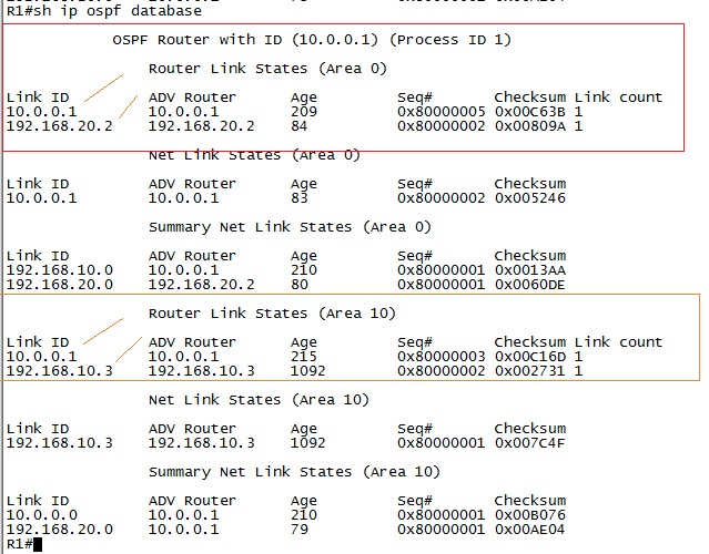
Note: As we can tell here this is a ABR since we have multiple instances of LSA's, one for each area. In this case it's for Area 0 and Area 10. For Area 0 R1 knows about all the Type 1 LSA's inside Area 0 and Area 10.
We have two type 1 LSA's inside Area 0 which is 10.0.0.1 (R1 link) and 192.168.20.2 (R2 link). Do remember that the Link ID is a 32-bit integer which by default will be the RID of the advertising router. This does not give you any more information than that. So keep that in mind when using this command to verify the OSPF topology.
We also have two type 1 LSA's inside Area 10 which is 10.0.0.1 (R1 link) and 192.168.10.3 (R3 link). Notice that we don't know about the Type 1 LSA's inside Area 20 which is connected to R2, we only know about the type 1 LSA's inside our own area.
To look at this from R3's perspective we should only have a topology for Area 10 where we should have two type 1 LSA's. One for R1 link and one for R3 link:
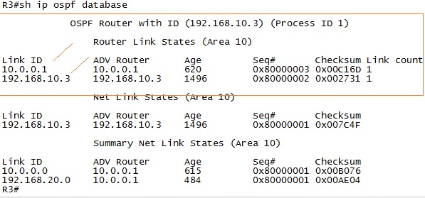
Note: As we can confirm here we have only two type 1 LSA's inside R3's topology database. The link 10.0.0.1 (R1) and 192.168.10.3 (R3). We don't know about area 0 and we don't know about area 20, all we know about is how our local area look like.
Important OSPF Design Note: This is why it's so important to segment a large OSPF topology into smaller areas since the Type 1 LSA's will only be stored from a single area. In which case the Area 0 must be able to support a much larger Link-State database since it will store LSA's from multiple areas!
OSPF LSA Type 2
LSA Type 2 - Network LSA
This is called "The Network LSA" and the purpose of the LSA Type 2 is to model a Link State DataBase Topology over a multiaccess-network such as Ethernet. To understand what that really means you would have to understand that OSPF needs to "draw a map of the topology" using only Link States between two nodes.
However in a multiaccess network such as Ethernet a single link could potentially connect to unlimited amount of nodes - because it's a shared segment and you may be able to reach multiple nodes over a single link on a shared segment.
But that doesn't follow the OSPF-rules that is supposed to keep track of the Link State between two nodes. So to solve that problem, on a Multiaccess network OSPF will use the Type 2 LSA's and flood them inside the area. The "Designated Router" is responsible for creating and advertising the Type 2 LSA's.
The Type-2 LSA includes the following information:
- The Link State Identifier is the DR's interface IP address in that subnet.
- The Designated Router's Router ID as the router advertising the LSA.
- The Type 1 LSA's that the Type 2 LSA connects to.
The Type 2 LSA is often call the "Transit Network" which can be identified by looking at Type 1 LSA's.
To understand why, we would have to once again do a short review of a Designated Router and what it does. Again the purpose of the designated router is to maintain a full Link State topology on a per network segment. This means that there can be multiple different Designated Routers inside the same single area.
It's very important to understand that the DR/BDR is elected per segment and not per area!
The problem that the DR solves is that on a Multiaccess network segment the DR and the BDR will have a full link-state topology of all nodes on that segment. Where every other router that's not elected DR or BDR will only know where the DR and the BDR is.
Without going into more details about the DR/BDR election process yet, a topology example will be easier to explain what the purpose is. So take this topology:
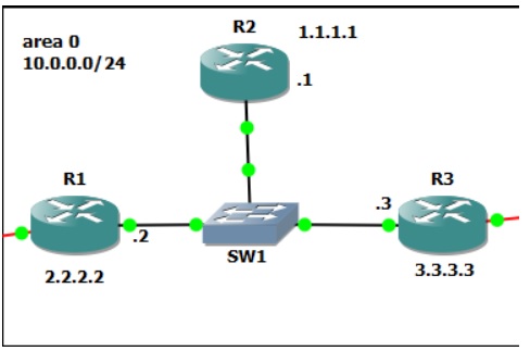
Take a look at this topology and think about what happens here. How would OSPF be able to draw a topology map for this network when all routers are connected to multiple nodes? (R1 links to R2 and R3, R2 to R1 and R3, R3 to R2 and R1)
Also note that a single subnet (10.0.0.0/24) is used on the shared segment. This is the problem that the DR/BDR will solve. The idea is that in this topology R3 will become the DR and R1 will become the BDR (based on the rules which is going to be studied in depth after LSA's).
This means that the DR will be the router that has the full topology information - or in OSPF terminology....all the Link State information to other nodes. So in this exact topology every router will have Type 1 LSA's from each other, since they're still in the same area 0.
But only R3 and R1 will know about all the nodes/networks inside Area 0. So R3 will create and flood the Type 2 LSA towards R1 and R2. From OSPF's point of view R3 will have a point-to-point link towards R1 and R2 - a full Link State information.
Again take a look at this topology:
It's crystal clear that there are multiple nodes sharing the same network segment here. Remember that Type 1 LSA's are flooded inside the same area to advertise about the links that are used by that router. So R1,R2,R3 will still generate Type 1 LSA's about their Links.
In this case R3 will advertise a Type 1 LSA with LSID 3.3.3.3, R2 with LSID 1.1.1.1 and R1 with LSID 2.2.2.2. The difference on this segment is that this is a Broadcast network where a DR/BDR is elected (Ethernet). So the Type 1 LSA's will from a logical point of view from OSPF be connected directly to the DR and the BDR.
So if you were to look at the Type 1 LSA from R2 in this topology, it will list it's Type 1 LSA as a "Transit Network" since it will transit through the DR first. If you look at this Type 1 LSA over at R1 or R3 you would find that everything is normal since both the DR and BDR have a full Link State topology.
Now what R3 will do is create the Type 2 LSA and advertise this into Area 0 and it will include information that this Type 2 LSA is connected to the Type 1 LSA from R2. It will also include the information that it's connected to the Type 1 LSA from R3 and R1.
So OSPF will view this topology like this:
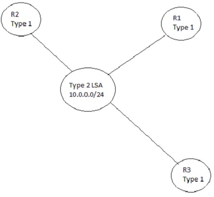
Looking at this image you can see that R1, R2 and R3 all have a point-to-point link towards the shared subnet of 10.0.0.0/24. Which is exactly what the Type 2 LSA is representing - a pseudorouter to represent the shared network.
Note: A sideeffect of using a DR and a BDR is that those are the only two routers on the entire network segment that will have a full topology view of the network. But that's not because of this, it has to do with the database Exchange process. Which will be covered more in the next section after LSA's.
OSPF note: As difficult as it is to explain, this means that R1,R2 and R3 will have a Type 2 LSA in the above topology example with LSID of 10.0.0.3 and the Advertising Router ID of 3.3.3.3.
To summarize the Type 2 LSA section, let's look again at the original multiarea topology:
Here we don't have enough information to decide which router will be DR and BDR. But in Area 10 there are 3 routers connected to the switch sharing that segment. There is also 3 routers connected to the switch in area 20 sharing that segment.
R1 and R2 are directly connected to each other, depending on the interface type used the default network will most likely be ethernet so a DR and BDR will also be elected.
This means that there will be a total of 3 Designated Routers and 3 Backup Designated Routers elected in that topology. In area 0 there will not be any Type 2 LSA.
Luckily for me I know OSPF enough to be able to tell which router will be elected as DR on all the segments based on the highest ip-address on a UP/UP interface on each router:
- -For area 0 R2 will be elected DR since it has address 192.168.20.2.
- -For area 10 R4 will be elected DR since it has address 192.168.20.4.
- -For area 20 R5 will be elected DR since it has address 192.168.20.5.
Important OSPF note/study note: This election assumes that the interfaces I will predict to become DR/BDR's will be up and running OSPF Before any other interfaces on that segment. We haven't discussed the election process in detail yet but it matters a lot with default settings how you enable OSPF. But for now, if all links are OSPF enabled at the same time highest IP-address will win the election.
To further break this down this means that R2,R4 and R5 will generate a Type 2 LSA for that network segment representing that subnet. So what we should see is the following Type 2 LSA's generated:
- -Area 10 should have a Type 2 LSA with LSID 192.168.10.4 and Advertised Router ID 192.168.20.4.
- -Area 20 should have a Type 2 LSA with LSID 192.168.20.4 and Advertised Router ID 192.168.20.4.
- -Area 0 should have a Type 2 LSA with LSID 10.0.0.2 and Advertised Router ID 192.168.20.2.
Only one way to confirm, check the LSDB on some routers!
Lets's check R1 first:

As this output confirms, in Area 0 we have the link id of R2 (the DR) which is 10.0.0.2. We also know the ADV Router which is 192.168.20.2 (highest ip address of an interface in the UP/UP state on R2/the DR).
Further more we can see that in Area 10 we have the link id of R4 (the DR) which is 192.168.10.4. We also know the ADV Router which is 192.168.20.4 (highest ip address of an interface in the UP/UP state on R4/the DR).
The same is going to be true for R2, where we can check Area 0 and Area 20:

Sure enough this work as predicted. R2 has the same Type 2 LSA as R1 for Area 0.
For area 20 we have the link id of R5 (the DR) which is 192.168.20.5. We also know the ADV Router which is 192.168.20.5 (highest ip address of an interface in the UP/UP state on R5/the DR).
Note: Although not covered yet, it's interesting to know that R4 is considered an OSPF ABR however that router does not link back towards area 0 - it's only connected to area 10 and area 20. So the backbone area would not be able to successfully map this topology, but that problem will be taken care of with the Type 3 LSA's which we will cover next.
As the final verification we can look inside the Type 2 LSA to view the Type 1 LSA's connected to the subnet. Let's look at R3 where we should see 3 Type 1 LSA's (R1, R3 and R4):
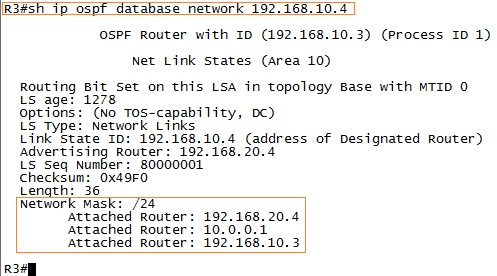
As we can tell from this output using the command "show ip ospf database network 192.168.10.4" we can see that this LSID represents a /24 subnet with three attached routers. The attached routers represents the Type 1 LSA's with the Router ID listed.
Sure enough, R3 seems to have a good view of Area 10.
Note: From a verification point of view this only tells us which Router ID is attached to the subnet. We would have to go to the DR to get a complete view of the topology since it has all the required information. However we can use the command "show ip ospf database router 192.168.20.4" to view more detailed information about a specific link. In this case since a DR is elected it will show this link as a "Transit Network" to indicate that a Type 2 LSA is maped to this Type 1 LSA.
Example output from R3 about the link state for 192.168.10.3:

Notice that OSPF knows that this is a Transit Network, since this Type 1 LSA is linked towards the Type 2 LSA that R4 generated in this area. So from OSPF's point of view this is a "stub network/transit network" that links towards the Type 2 LSA that the DR advertised and generated.
daniel.larsson- Admin
- Posts : 47
Join date : 2015-04-30
Age : 41
Location : Boras, Sweden -
Layer 3 - Open Shortest Path First PART 5
![]() by daniel.larsson Mon Aug 17, 2015 11:09 pm
by daniel.larsson Mon Aug 17, 2015 11:09 pm
Technology:
- OSPF LSA Type 3
Open Shortest Path First PART 5
(OSPF LSA Type 3)
Notes Before reading: Now we will tear OSPF apart and put it back again to see what is really happening under the hood/behind the scenes with this protocol.
This section will be complicated and requires that you fully understand the basics of OSPF before moving on. Here we will look at what happens inside every single area when using OSPF, we will not be looking at what happens outside areas yet - so bear with me, I think you will be amazed.
Like before all of these topics are covered in CCNP but not at the depth required to become CCIE. But I prefer the CCNP-books for this topic and the OSPF RFC's for references of how OSPF is supposed to be working (although cisco implements it slightly different).
If it's not already crystal clear I will repeat myself.
OSPF is a very complex protocol and a very difficult one to master. Even if I consider myself very skilled at OSPF I think I will run into many situations here that are new. Many of the new topics are considered network optimization topics that requires a solid understanding of how OSPF actually work behind the scenes before going into that area.
OSPF LSA Type 3
1. I believe that OSPF Type 3 LSA's are covered fairly good in the CCNP-books. The only problem is that the explanations of how it actually work behind the scenes are easily missed. I still recommend the CCNP books for this section mainly because it's not overcomplicated things to understand, but be warned - it's easy to miss in the book so check the RFC if you think you need a better explanation. It really depends on your background knowledge and experience with OSPF.
Like many times before, I still believe that there is no better book than the CCNP ROUTE by Wendel Odom.
With Type 3 LSA's we're also slowly progressing with OSPF and going into the details of how OSPF works outside it's areas and how to tell OSPF-routers how the network look like in other areas. So it might be good to also read the CCIE RSv5 Official Certification guide for this section.
It might also not be enough to fully understand what's happening so you may have to look elsewhere for a good explanation as well. Again we are moving into a complete demonstration about how LSA type 3 will work, so beware!
Book: CCNP ROUTE Official Certification Guide, Chapter 5-6.
Chapter 5 is named: OSPF Overview and Neighbor Relationships.
Chapter 6 is named: OSPF Topology, Routes and Convergence.
Since it only covers some part of the OSPF-technologies in the blueprint, i will also have to look at the official Certification Guide:
Book: CCIE RSv5 Official Certification Guide, Chapter 9.
Chapter 8 is named: OSPF.
Note: It's also possible that you may want to read some RFC's about OSPF and some other sites explaining what the LSA Type 3 actually do. Beware though, many many places simplify what is happening. And for CCIE it's required to have a solid understanding, not just a bit about how it works.
IP Routing - OSPF Configuration Guide Link: http://www.cisco.com/c/en/us/td/docs/ios-xml/ios/iproute_ospf/configuration/15-mt/iro-15-mt-book.html
Note: There is just so, so much to read about OSPF so there's no good and accurate configuration guides to point towards. Since almost every single topic of OSPF has it's own configuration guide, like LSA 1, LSA2, LSA3 etc.
Learned:
-That there's too much information about OSPF to actually be able to learn any topics from the configuration guides. However they're well worth a read-through to see how Cisco implements OSPF compared to the RFC-standard. Which we will see - they make a few changes along the way.
OSPF LSA Type 3
LSA Type 3 - Summary LSA
This is called "The Summary LSA" and the purpose of the LSA Type 3 is to reduce the number of Type 1 and Type 2 LSA's in a OSPF network domain. OSPF do this by the concept of what is called the "Area Border Router".
Before moving on here it's required to define what exactly the Area Border Router is within OSPF. But this is not as easy as it may sound. Because the definition of what an Area Border Router is will be different depending on which OSPF implementation the vendor choose to follow.
So I will define what an Area Border Router is based on the OSPF Standard and the Cisco and IBM Terminology.
ABR Definition in the OSPF Standard RFC2328:
RFC2328 wrote:"A router that attaches to multiple areas. Area border routers run multiple copies of the basic algorithm, one copy for each attached area. Area border routers condense the topological information of their attached areas for distribution to the backbone. The backbone in turn distributes the information to the other areas. "
Interesting note: This more or less states that as long as the router connects to at least two areas it's considered to be an ABR. It will summarize the subnet from one area and advertise it into the other areas. But for traffic to flow between two different areas (inter-area traffic) the traffic must flow through the backbone area.
Cisco's ABR Definition in Alternative Implementations of OSPF Area Border Routers stated in RFC3509:
This RFC basically redefines what the ABR is and does. The first quote from this RFC is to explain what exactly Cisco changes to the OSPF behaviour.
RFC3509 by Cisco wrote:"The next section describes alternative ABR behaviors, implemented in Cisco and IBM routers. The changes are in the ABR definition and inter-area route calculation. Any other parts of standard OSPF are not changed.
These solutions are targeted to the situation when an ABR has no backbone connection. They imply that a router connected to multiple areas without a backbone connection is not an ABR and should function as a router internal to every attached area. This solution emulates a situation where separate OSPF processes are run for each area and supply routes to the routing table. It remedies the situation described in the examples above by not dropping transit traffic. Note that a router following it does not function as a real border router---it doesn't originate summary-LSAs. Nevertheless such a behavior may be desirable in certain situations."
That sure is some interesting things here that Cisco changes. At least if you are not paying attention to what it's really saying. It completely tells you that "a router following it does not function as a real border router - it doesn't originate summary LSA's".
By itself that really means that it's not even considerd to be an ABR at all.
So what eactly did Cisco change to the ABR behaviour?
They did change the definition so that the ABR must have an active connection to at least two different areas and one of them must be the backbone area 0. Otherwise the router will just be considered as a normal active router in that area.
Here's the quote:
Cisco wrote:"Actively Attached area:
An area is considered actively attached if the router has at least one interface in that area in the state other than Down.
Cisco Systems Interpretation:
A router is considered to be an ABR if it has more than one area Actively Attached and one of them is the backbone area."
Without knowing these facts the topology i've been using to demonstrate the OSPF behavior will run into some trouble over at R4. Not only does R4 not become the ABR in a Cisco network - it will only become ABR if an interface in the backbone area are NOT down.
IBM's ABR Definition in Alternative Implementations of OSPF Area Border Routers stated in RFC3509:
This RFC basically redefines what the ABR is and does. The first quote from this RFC is to explain what exactly IBM changes to the OSPF behaviour.
RFC3509 by IBM wrote:"The next section describes alternative ABR behaviors, implemented in Cisco and IBM routers. The changes are in the ABR definition and inter-area route calculation. Any other parts of standard OSPF are not changed.
These solutions are targeted to the situation when an ABR has no backbone connection. They imply that a router connected to multiple areas without a backbone connection is not an ABR and should function as a router internal to every attached area. This solution emulates a situation where separate OSPF processes are run for each area and supply routes to the routing table. It remedies the situation described in the examples above by not dropping transit traffic. Note that a router following it does not function as a real border router---it doesn't originate summary-LSAs. Nevertheless such a behavior may be desirable in certain situations."
IBM does a simular change to the ABR definition like Cisco, except their definition is:
IBM wrote:"Configured area:
An area is considered configured if the router has at least one interface in any state assigned to that area.
Actively Attached area:
An area is considered actively attached if the router has at least one interface in that area in the state other than Down.
IBM Interpretation:
A router is considered to be an ABR if it has more than one Actively Attached area and the backbone area Configured."
This means that when you think about how OSPF work, make sure that you know how the vendor of your choise is implementing OSPF - because it may affect the connectivity in your network.
When talking about OSPF in general i will claim that the ABR is just a router that is connected to multiple areas. That's what the standard implies, but as we just learned Cisco implements this a different way.
Using the same topology as before - R1, R2, R4 will be considered ABR's by OSPF. That means that by design they will not flood the Type 1 and Type 2 LSA's from one area to another area. Instead they create a "Type 3 Summary LSA" for each subnet it's connected to and flood these Type 3 LSA's into the other areas.
The logic is that if there is a link-state change in area 10 it should not affect Area 0 or area 20. But area 10 and area 20 would still need to be able to reach eachother somehow. By OSPF logic all they would need to know is where the ABR is located and the ABR knows how to forward the packet further.
Also once the ABR advertised the Type 3 LSA into an area the other routers will keep flooding this Type 3 Summary LSA into other areas and to other routers so the complete OSPF domain knows how to reach this ABR.
Intersting key thing about how OSPF work: This is a rather interesting concept with OSPF. Because by doing so, OSPF can arguably be called a hybrid protocol since when using ABR's Type 3 Summary LSA's you are in fact routing by rumor using the same concept as Distance Vector routing protocols. You are trusting the ABR, you don't know the exact details other than how to reach the ABR.
OSPF Design Note: It's interesting to meantion that by design the ABR will block Type 1 and Type 2 LSA's from spreading futher in your OSPF topology. The effect you get when creating a ABR is that it will limit the Type 1 and Type 2 LSA's flooding domain. It's like a Router for limiting broadcast domains.
So to fully understand this concept, let's look at which information the Type 3 LSA will carry.
The Type-3 LSA includes the following information:
- -The Link State Identifier is the subnet number that's advertised by the ABR.
- -The Advertised Router is the Router ID of the ABR.
I will be using the same topology as before to demonstrate where Type 3 LSA's will be generated:
Same topology as before. R1, R2 and R4 are considered ABR's by OSPF terminology. It just means that they are connected to multiple areas. ABR's are the only routers in OSPF that will be able to generate Type 3 LSA's because the idea is to not flood Type 1 and Type 2 LSA's from one area (10 for example) into a different area (20 for example).
So to still keep the topology map that OSPF uses complete, the ABR's will tell the other areas which subnets are reachable through the ABR's. What that really does is that it will map the subnets that the ABR can reach and turn them into a specific LSA-type that the other areas will learn.
Normally inside the area the Type 1 LSA's would identify links, or the Type 2 LSA would identify which Type 1 LSA's you can reach through the Type 2 LSA. Not in this case! The Type 3 LSA will identify which subnet is reachable through the advertised router!
That's a very important piece of information to understand!
So by looking at the topology and based on the rules OSPF uses I can tell that the following Type 3 LSA's should be generated and by which router:
R1
-Should generate a Type 3 LSA for the subnet 192.168.10.0/24 and flood that into Area 0. The LSID would be 192.168.10.0 and the ADV RID would be 192.168.10.1.
-Should generate a Type 3 LSA for the subnet 10.0.0.0/24 and flood that into Area 10. The LSID would be 10.0.0.0 and the ADV RID would be 192.168.10.1.
R2
-Should generate a Type 3 LSA for the subnet 192.168.20.0/24 and flood that into Area 0. The LSID would be 192.168.20.0 and the ADV RID would be 192.168.20.1.
-Should generate a Type 3 LSA for the subnet 10.0.0.0/24 and flood that into Area 20. The LSID would be 10.0.0.0/24 and the ADV RID would be 192.168.20.1.
R4
-Should generate a Type 3 LSA for the subnet 192.168.10.0/24 and flood that into Area 20. The LSID would be 192.168.10.0 and the ADV RID would be 192.168.20.4.
-Should generate a Type 3 LSA for the subnet 192.168.20.0/24 and flood that into Area 10. The LSID would be 192.168.20.0 and the ADV RID would be 192.168.20.4.
Important things to notice: In this special topology there will be generated multiple Type 3 Summary LSA's for the different subnets. Especially in Area 10 and 20. The interesting thing here is that R4 will generate the same Type 3 LSA that R1 and R2 would do.
In other words, Area 0 should know about 192.168.10.0/24 and 192.168.20.0/24 from two different ADV RID. R4 will advertise about 192.168.10.0/24 into Area 20. R2 will know about 192.168.10.0/24 from R1 as well. And vice versa for the 192.168.20.0/24 network.
More importantly - How will OSPF work when this happens? There sure are some conflicting decisions to be made or this will not work. Obviously both paths would not be able to be used since there will always be a "best path".
I put that in quotes because it really depends on the OSPF configuration itself! If the actual OSPF cost would be equal along both paths, then mutual load redistribution would be in effect! Or what's called Equal Cost Load Balancing.
Let's verify and see what's happening, starting with R1:
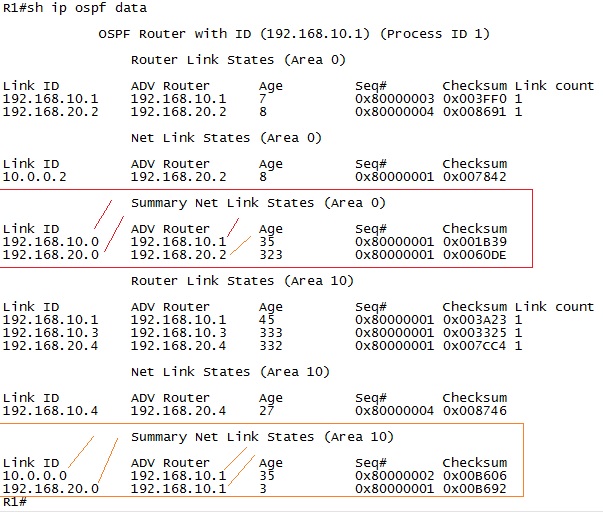
As predicted there are a couple of Type 3 LSA's on R1. Here's some very interesting facts about the output:
-For Area 0 we can see that R1 generated the Type 3 LSA for network 192.168.10.0/24 with itself as the RID (192.168.10.1) to reach this network.
-For Area 0 we can also see that R2 generated a Type 3 LSA for network 192.168.20.0/24 with itself as the RID (192.168.20.2) to reach this network.
-For Area 10 we can see that R1 generated the Type 3 LSA for network 10.0.0.0/24 with itself as the RID (192.168.10.1) to reach this network.
-For Area 10 we can also see that R1 generated the Type 3 LSA for network 192.168.20.0/24 with itself as the RID (192.168.10.1) to reach this network.
Important interesting OSPF topology information:
-What we cannot see over at R1 is the Type 3 LSA from R4 inside Area 0.
By the OSPF rules and design - the Type 3 LSA that R4 generates, because it's ABR, should be flooded across the entire OSPF domain. So why doesn't R1 learn about this LSA in Area 0 but it does for area 10?
It's actually a very interesting topic to discuss because this is one of those topics where cisco, being a T-Rex in the foodchain of networks, decided to NOT follow the RFC/standard for OSPF. Look at the topology again:
By just following the OSPF-rules for how the SPF-is calculated, the rules to become Area Border Router is to simply have interfaces in more than one area. Surely R4 qualifies for this and you would expect R4 to advertise Type 3 LSA's.
However Cisco's implementation of OSPF breaks this rule.
On a Cisco router the ABR must have at least one Active interface in Area 0 to be considered ABR.
This means that from the perspective of OSPF running on Cisco routers there will be no Type 3 LSA's generated at all from R4 since it doesn't have any interfaces in Area 0. That means that it's just considered to be part of area 10 with one interface and part of area 20 with the other interface.
So if we play with the idea that traffic were to flow from R4 area 20 interface (192.168.20.4) towards R3 area 10 interface (192.168.10.3) the traffic would have to flow over area 0 and then into area 10. Now this is not the case since from R4's perspective the destination network is directly connected to R4. To demonstrate this you would actually have to have at least one router-hop more on that area.
But if you were to ping from R5 to R3 the traffic would flow through area 0:
R5#traceroute 192.168.10.3
Type escape sequence to abort.
Tracing the route to 192.168.10.3
VRF info: (vrf in name/id, vrf out name/id)
1 192.168.20.2 1 msec 1 msec 0 msec
2 10.0.0.1 1 msec 0 msec 1 msec
3 192.168.10.3 1 msec * 1 msec
R5#
The same would be true if you would be able to generate traffic from R4's interface in area 20 without R4 knowing about the directly connected network in area 10. This is just in theory since i don't know a single way to configure that, it's just for the sake of the discussion to explain that on a Cisco router inter-area traffic will always flow through area 0.
This can't be confirmed in the topology i used to demestrate this as an example.
I used that topology because R4 would work differently than the standard implies that it should because Cisco changed that router's behaviour to just be a zomie in each area it's attached to - don't generate Type 3 LSA's because you don't belong to area 0.
daniel.larsson- Admin
- Posts : 47
Join date : 2015-04-30
Age : 41
Location : Boras, Sweden -
Layer 3 - Open Shortest Path First PART 6
![]() by daniel.larsson Thu Aug 20, 2015 12:16 pm
by daniel.larsson Thu Aug 20, 2015 12:16 pm
Technology:
- OSPF LSA Type 4
Open Shortest Path First PART 6
(OSPF LSA Type 4)
Notes Before reading: This starts the discussion of how OSPF will work outside it's own network. In other words, how OSPF will treat networks that are in a different routing-domain, such as RIP or ISP-redistributed networks.
This section goes on with the LSA-types and makes it more complicated. We will be looking at how the various LSA-types interact to map the external networks. First with LSA Type 4 and then directly moving on to LSA type 5. Both of these LSA-types can be very difficult to understand how they work, so you need a good understanding of the basics of how OSPF will work to understand this!
These topics on the other hand are NOT covered good in the CCNP book. They are covered, but just a tiny bit - not barely enough to pass the CCNP-exams so that's the only downside with that book. For this part you would therefor have to look into some CCIE-studies (like blogs) or the CCIE RSv5 Official Certification Guide book. It does a very good job at explaining how this works.
If it's not already crystal clear I will repeat myself.
OSPF is a very complex protocol and a very difficult one to master. Even if I consider myself very skilled at OSPF I think I will run into many situations here that are new. Many of the new topics are considered network optimization topics that requires a solid understanding of how OSPF actually work behind the scenes before going into that area.
OSPF LSA Type 4
1. As I said before (above) the Type 4 LSA's are not well covered in the CCNP-books. So this means that you would have to look into the CCIE books to get a good grasp of how it happens and why.
The RFC also explains how it works and as we already know, Cisco redefines what the ABR is and does so beware of that when reading the official OSPF RFC! It doesn't affect the ASBR/Type 4 LSA's, however since the ASBR might also be the ABR you would want to look into the RFC and understand what cisco changed to the ABR behaviour.
I will try and really tear apart and show you exactly how the Type 4 LSA work here so there shouldn't be any need to look elsewhere, but if you are interested - the RFC is always a good place to look. Cisco also has a lot of good documentation about OSPF.
So let's move on to do a complete demonstration about what the Type 4 LSA is and how it works. It will be complicated, so be warned!
Book: CCIE RSv5 Official Certification Guide, Chapter 9.
Chapter 8 is named: OSPF.
Note: It's also possible that you may want to read some RFC's about OSPF and some other sites explaining what the LSA Type 4 actually do. Beware though, many many places simplify what is happening. And for CCIE it's required to have a solid understanding, not just a bit about how it works.
IP Routing - OSPF Configuration Guide Link: http://www.cisco.com/c/en/us/td/docs/ios-xml/ios/iproute_ospf/configuration/15-mt/iro-15-mt-book.html
Note: There is just so, so much to read about OSPF so there's no good and accurate configuration guides to point towards. Since almost every single topic of OSPF has it's own configuration guide, like LSA 1, LSA2, LSA3 etc.
Learned:
-That there's too much information about OSPF to actually be able to learn any topics from the configuration guides. However they're well worth a read-through to see how Cisco implements OSPF compared to the RFC-standard. Which we will see - they make a few changes along the way.
OSPF LSA Type 4
LSA Type 4 - Summary ASBR LSA's
This is called "The Summary ASBR LSA" and the purpose of the LSA Type 4 is to tell the OSPF domain where the "Autonomous System Border Router" is located. The only purpose that this LSA type has is to inform the rest of the OSPF domain where the router is that is connected to an external network/a different Autonomous System.
Simular to the Type 3 Summary LSA before moving on here it's required to define what exactly the Autonomous System Border Router is and how OSPF defines it. It's easy enough to define what the ASBR and the requirements to become ASBR is, what's less easy to understand is how the OSPF domain creates, advertises and floods the Type 4 LSA inside the OSPF domain!
ASBR Definition in the OSPF Standard RFC2328
RFC2328 wrote:AS boundary routers
A router that exchanges routing information with routers belonging to other Autonomous Systems. Such a router advertises AS external routing information throughout the Autonomous System. The paths to each AS boundary router are known by every router in the AS. This classification is completely independent of the previous classifications: AS boundary routers may be internal or area border routers, and may or may not participate in the backbone.
That is simple enough, as long as the router is connected to any external system it is to be considered an Autonomous System Border Router. But what makes this type of LSA very difficult to completely break down and understand how it actually works is that the documentation is very vague, and not many sources of information exists to get the exat details of how it works.
To give a very brief and short explanation - the router that is an ASBR will create a Type 1 LSA with a special bit fliped to 1 to tell the other routers that this router is connected to an external system. This is done in the Type 1 Router LSA's themselves, by fliping what's called the External bit (E-bit) in the LSA-packet.
This is some really difficult information to come by but to explain what happens we need to first have a look at how the Type 1 LSA-packet format look like again:

As this image sort of indicates, but very vaguely, there are some special bits called the V|E|B bits that can be either fliped (1) or not fliped (0) in this packet. We can call these ther "Router LSA flags" to easier understand that they're flags that can be set.
Most images explaining the LSA types would not show you this image, but instead the 0|V|E|B fields would be replaced with a "FLAGS" field to indiate that there are some things that can be set in this LSA type.
This is a very interesting concept because the way that OSPF will know that you are either the ASBR (Autonomous System Border Router), the ABR (Area Border Router) or the endpoint of what's called "OSPF Virtual Link" - is by looking at these bits in the Type 1 LSA's.
And it makes sense. Since the purpose of the Type 1 LSA is to identify all links in that area, looking at this LSA every other router will know that this router is either connected, or not connected, to another area or AS-system or to a Virtual-Link.
So to demonstrate how this actually works now that you know this is done using Type 1 LSA's then let's look at a topology example that would generate a Type 4 LSA:
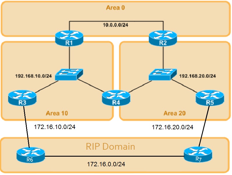
In this altered topology we have R3 and R5 as the ASBR's from the OSPF point of view.
It's difficult to grasp what the Type 4 LSA actually does. What I mean by that is that you would easily think that R3 and R5 would be the router generating the Type 4 LSA.
But that's not the case. What R3 and R5 actually does is that it will use the Type 1 LSA flags to "flag" that they are ASBR's in that area. What happens next is that once the Type 1 LSA reaches the ABR the ABR is the router that generates the ASBR Type 4 LSA and flood it to the other areas.
In this topology it means that R1 and R2 would receive Type 1 LSA's with the E-bit flag fliped (binary 1) to indicate that the Type 1 LSA from R3 and R5 are connected to a different Autonomous System.
So R1 and R2 will then create, generate and advertise the Type 4 LSA and flood them inside the Backgone area and towards the other Areas. This means that Area 10 will receive a Type 4 LSA pointing towards R5, Area 20 will receive a Type 4 LSA pointing towards area 10.
The backbone area will contain both Type 4 LSA's since they are both advertised into Area 0. However Area 10 and Area 20 should only receive one Type 4 LSA each. That's because the local area already knows, based on the E-bit in the Type 1 LSA, that this area has a local ASBR. So there is no point in flooding the Type 4 LSA inside the area where the ASBR exists.
The point with the Type 4 LSA is to tell the rest of the OSPF network (meaning all other areas except the local area where the ASBR belongs) where the ASBR is located. Since it's not the actual ASBR that advertises this LSA, it means that from the rest of the network it will say that the ASBR is reachable through the ABR that advertised the Type 4 LSA.
So to completely understand how the Type 4 LSA work it's required to know which information is included in the Type 4 LSA.
The Type-4 LSA includes the following information:
-The Link State Identifier is the Router ID of the ASBR.
-The Advertised Router is the Router ID of the ABR.
I will be using the slightly altered topology with a RIP domain to demonstrate how Type 4 LSA's are generated:
Pretty obvious that R3 and R5 are ASBR's here and R1 and R2 are ABR's. Based on that information we should be able to tell which LSA's would be generated and where. R3 and R5 are ASBR's becuase they connect to the external autonomous system, in this case RIP. R1 and R2 and R4 are ABR's since they connect to multiple areas.
Note about Cisco implementation of OSPF: Remember that Cisco's implementation of OSPF does not treat R4 as an ABR, but just a link in both areas that it has interfaces configured for.
But following the OSPF standard then R4 would be an ABR and actually create a Type 4 LSA in this case - since the standard doesn't actually force the ABR to be a member of Area 0. We will see if that's the case or not as well!
Important configuration change to generate Type 4 LSA's:
We haven't discussed what a Type-5 LSA is yet, but the short version is that it represents external networks. And you won't be able to generate Type 4 LSA's without having some external networks to route towards.
So a slight configuration change is made on R3 and R5 to generate external routes:
!R3
configure terminal
router ospf 1
redistribute rip
!
!R5
configure terminal
router ospf 1
redistribute rip
Without at least one external network inside the OSPF domain there is no point in generating Type 4 LSA's so without External networks going into the OSPF domain the ASBR's wont set the E-bit in the Type 1 LSA's.
Since we're talking about Type 4 LSA's in this section i will just keep it to explain how Type 4 LSA's work and ignore the Type 2/3 LSA's also generated.
R3
-Will generate a Type 1 LSA with Link-State ID of 192.168.10.3 (the ip-address of the link in area 10) with a Advertised Router of 192.168.10.3 (the Router ID of R3).
-Will also set the E-bit in the Type 1 LSA since it's connected to the RIP-domain. This will flag this link as a "AS Boundary Router".
-Will receive a Type 4 LSA from R1 with Link-State ID of 192.168.20.5 and with a Advertised Router of 192.168.10.1
R5
-Will generate a Type 1 LSA with Link-State ID of 192.168.20.5 (the ip-address of the link in area 20) with a Advertised Router of 192.168.20.5 (the Router ID of R5).
-Will also set the E-bit in the Type 1 LSA since it's connected to the RIP-domain. This will flag this link as a "AS Boundary Router".
-Will receive a Type 4 LSA from R2 with Link-State ID of 192.168.10.3 and with a Advertised Router of 192.168.20.2.
R1
-Will generate and advertise a Type 4 LSA into Area 0 with Link-State ID of 192.168.10.3 and with the Advertised Router of 192.168.10.1
-Will receive a Type 4 LSA from R2 and flood this into Area 10. This will have a Link-State ID of 192.168.20.5 and with the Advertised Router of 192.168.20.2.
R2
-Will generate and advertise a Type 4 LSA into Area 0 with Link-State ID of 192.168.20.5 and with the Advertised Router of 192.168.20.2
-Will receive a Type 4 LSA from R1 and flood this into Area 20. This will have a Link-State ID of 192.168.10.3 and with the Advertised Router of 192.168.10.1.
Note: the command used is "show ip ospf database router 192.168.10.3" to look at specifically the Type 1 LSA on the R3 link 192.168.10.3.
So let's verify if that's actually happening by first looking at the Type 1 LSA that R1 generated before external networks are present:

Nothing spectacular about this output, everything is expected there it just points to the DR (R4 in this case) and flags this link as a transit network. No information about whether or not this link attaches to any external networks.
Now let's do the same check after introducing the RIP routes to the OSPF domain by redistributing them inside the OSPF domain:

Notice the very interesting fact that now OSPF flags this link as "AS Boundary Router".
Which indicates that this Type 1 LSA has the E-bit set (which if you look at how the Type 1 LSA packet format is - directly after the Length-field. Cisco routers are smart enough to not show you this information unless the bits are fliped/set which is why it was not included in the first output when all the bits were 0 in the flag-field)
The exact same scenario will be true from R2's perspective towards the link of R5 (192.168.20.5).
Important OSPF Note: Type 1 LSA's are local to the area only, so you wouldn't be able to view this piece of information for other areas, obviously. Easily missed though since we are actually talking about Type 4 LSA's!
For the final part of the verificaion it's important to understand that the ABR's (R1 and R2) will generate a Type 4 LSA to the other areas based on whether or not the Type 1 LSA has the E-bit set and flaged as AS Boundary Router.
Very important for understanding OSPF since it's not the ASBR that generates this LSA. It's the ABR that generates the Type 4 LSA's when advertising to other areas that they know about the ASBR router.
So the final verification will be that R3 has received the Type 4 LSA that points towards Area 20 and that R5 has received the Type 4 LSA that points towards Area 10.
It's also a good idea to check if R1 and R2 knows about both Type 4 LSA's since they should be having both LSA's inside Area 0.
R1:

Confirmed, for Area 0 R1 knows about both the Type 4 LSA's and for Area 10 it needed to only know about the Type 4 LSA that R2 generated.
Note: The Type 4 LSA that leads to area 20 actually points to R1 from the perspective of routers inside Area 10 since R1 flooded that LSA to area 10!
R2:

Confirmed, for Area 0 R2 knows about both the Type 4 LSA's and for Area 20 it needed to only know about the Type 4 LSA that R1 generated.
Note: The Type 4 LSA that leads to area 10 actually points to R2 from the perspective of routers inside Area 20 since R2 flooded that LSA to area 20!
R3:

Confirmed, for Area 10 R3 knows only about the Type 4 LSA that R2 initially generated.
Note: The Type 4 LSA that leads to area 20 actually points to R1 from the perspective of routers inside Area 10 since R1 flooded that LSA to Area 10.
R5:

Confirmed, for Area 20 R5 knows only about the Type 4 LSA that R1 initially generated.
Note: The Type 4 LSA that leads to area 10 actually points to R2 from the perspective of routers inside Area 20 since R2 flooded that LSA to Area 20.
Final conclusion about Type 4 LSA's
Wow. This was a lot to take in and an extremely difficult topic to fully grasp since the Type 4 LSA is simply put is just a helper-address at the end of the day to reach the next type of LSA - the Type 5 LSA's that represents an External network.
The logic is that routers inside the local area only need to know how to forward towards their ABR (hence the ABR set it's own RID as the Advertised Router). The ABR in turn looks in it's own Database to see how to forward traffic towards the ASBR.
In this case to get from R3 to ASBR R5 it would look up 192.168.20.5 and see that it should calculate a path towards RID 192.168.10.1 (which is R1).
R1 will then look in it's own database and calculate a path to reach RID 192.168.20.2 (since it has a Type 4 LSA from R2 for the ASBR 192.168.20.5).
R2 will then look in it's own database and calculate a path to reach RID 192.168.20.5, it's local to R2 in area 20 so it will look at the Type 1 LSA to calculate the path towards R5.
Again the idea is to simplify the OSPF link-state database with a Summary of how to reach the ASBR's through ABR's - each and every router does not need to know the complete link-state topology to reach ASBR's, all they need to know is how to forward to the ABR's which in turn can be directly connected to the area where the ASBR is located or it can be needed to further forward the packet.
Special important note about Cisco OSPF networks: This is how it works in Cisco's implementation of OSPF, it does not follow the standard since by definitions R4 will not become ABR and will not generate or flood any Type 4 LSA's. Running a code that completely complies with the OSPF standard then R4 would in fact become ABR and generate, create and flood Type 4 LSA's.
daniel.larsson- Admin
- Posts : 47
Join date : 2015-04-30
Age : 41
Location : Boras, Sweden -
Layer 3 - Open Shortest Path First PART 7
![]() by daniel.larsson Sat Aug 29, 2015 8:02 pm
by daniel.larsson Sat Aug 29, 2015 8:02 pm
Technology:
- OSPF LSA Type 5
Open Shortest Path First PART 7
(OSPF LSA Type 5)
Notes befire reading: This starts the discussion of how OSPF will work outside it's own network. In other words, how OSPF will treat networks that are in a different routing-domain, such as RIP or ISP-redistributed networks.
This section goes on with the LSA-types and makes it more complicated. We will be looking at how the various LSA-types interact to map the external networks. In the previous part we covered the LSA Type 4 which is basically just tells routers where the External network is located. This means that the Type 4 LSA contains information how to reach the Type 5 LSA.
Both of these LSA-types can be very difficult to understand how they work, so you need a good understanding of the basics of how OSPF will work to understand this!
These topics on the other hand are NOT covered good in the CCNP book. They are covered, but just a tiny bit - not barely enough to pass the CCNP-exams so that's the only downside with that book. For this part you would therefor have to look into some CCIE-studies (like blogs) or the CCIE RSv5 Official Certification Guide book. It does a very good job at explaining how this works.
If it's not already crystal clear I will repeat myself.
OSPF is a very complex protocol and a very difficult one to master. Even if I consider myself very skilled at OSPF I think I will run into many situations here that are new. Many of the new topics are considered network optimization topics that requires a solid understanding of how OSPF actually work behind the scenes before going into that area.
OSPF LSA Type 5
1. Just as with the Type 4 LSA the Type 5 LSA is not covered wll in the CCNP-books. However they are fairly good covered and you will get a great understanding of how it works and what it is. But what you don't get any understanding of is how it works behind the hood - in other words, there is no use
As I said before (above) the Type 4 LSA's are not well covered in the CCNP-books. So this means that you would have to look into the CCIE books to get a good grasp of how it happens and why.
The RFC also explains how it works and as we already know, Cisco redefines what the ABR is and does so beware of that when reading the official OSPF RFC! It doesn't affect the ASBR/Type 4 LSA's, however since the ASBR might also be the ABR you would want to look into the RFC and understand what cisco changed to the ABR behaviour.
I will try and really tear apart and show you exactly how the Type 5 LSA work here so there shouldn't be any need to look elsewhere, but if you are interested - the RFC is always a good place to look. Cisco also has a lot of good documentation about OSPF.
So let's move on to do a complete demonstration about what the Type 5 LSA is and how it works. It will be complicated, so be warned!
Book: CCIE RSv5 Official Certification Guide, Chapter 9.
Chapter 8 is named: OSPF.
Note: It's also possible that you may want to read some RFC's about OSPF and some other sites explaining what the LSA Type 5 actually do. Beware though, many many places simplify what is happening. And for CCIE it's required to have a solid understanding, not just a bit about how it works.
IP Routing - OSPF Configuration Guide Link: http://www.cisco.com/c/en/us/td/docs/ios-xml/ios/iproute_ospf/configuration/15-mt/iro-15-mt-book.html
Note: There is just so, so much to read about OSPF so there's no good and accurate configuration guides to point towards. Since almost every single topic of OSPF has it's own configuration guide, like LSA 1, LSA2, LSA3 etc.
Learned:
-That there's too much information about OSPF to actually be able to learn any topics from the configuration guides. However they're well worth a read-through to see how Cisco implements OSPF compared to the RFC-standard. Which we will see - they make a few changes along the way.
OSPF LSA Type 5
LSA Type 5 - Autonomous System External LSA
This is called "The Autonomous System External LSA" and the purpose of the LSA Type 5 is to tell the OSPF domain where External routes are located that exists outside the OSPF domain/topology.
Having already defined and discussed how the ASBR is defined and identified in the Type 4 LSA section, we can proceed and look at the topology with the RIP-domain again.
One important thing to consider when talking about Type 5 LSA's are that - no Type 5 LSA's will be generated as long as you are not injecting any external routes into the OSPF Domain.
To inject external routes it's therefor a requirement to use redistribution to generate Type 5 LSA's. Type 1-3 LSA's are created to map the topology internal to the OSPF domain, whereas Type 4-5 and 7 are used to map the topology external to the OSPF domain.
So without having any kind of external networks to route towards, we can't generate any Type 5 LSA's. The problem with understanding what the Type 5 LSA actually does is that it has a few traffic engineering fields that are not commonly used, but sure enough needs to be covered for CCIE studies.
So let's have a look at what type of information you can expect to see in the Type 5 LSA. Here's the LSA header:

There are a couple of interesting fields here that has to do with traffic engineering.
Mainly the field "Forwarding Address" is what most people have trouble with when talking about OSPF and Type 5 LSA's.
We will of course be discussing what it's used for, but for now let's just say that the Type 5 LSA is where most people get in trouble when discussing networking traffic engineering possibilities.
Note: I've actually seen quite a few people discuss what the Type 5 LSA is, does and how it handles the Metric (cost for OSPF). It seems this is a very mystifying topic for many people. And it really is a bit difficult to grasp because when dealing with External networks - OSPF will treat the advertised prefixes differently depending on how you traffic engineer them to work.
Note: By generating the Type 5 LSA we are also generating a Type 4 LSA that links directly to the Type 5 LSA. The type 4 LSA is helping OSPF routers learn how to route towards the Type 5 LSA-network that was injected, but we'll learn more about that in a moment.
To completely understand how the Type 5 LSA work it's required to know which information is included in the Type 5 LSA. There is a lot of information in this LSA-type, and only a few of the fields are used commonly. Most of the optional fields are used for traffic engineering, but let's cover all the options very briefly before puting down a list that includes the information you are most likely to see in the OSPF topology database.
The Type 5 LSA-fields can hold the following information:
-Link-State ID
-Advertising Router
-The Network Mask/Prefix
-The E,F,T bits (part of the External metric that is advertised, this only uses the External type for OSPFv2 (IPv4) but uses E,F,T bits for OSPFv3 (IPv6))
-The metric
-Forwarding Address
-External Route Tag
Some of these fields require a short discussion, we will not dig too deep into what they are and how you use them. However most of these fields can be used to traffic engineer your OSPF domain. They're mainly used to tell your internal OSPF-routers how to forward traffic to the External network.
So to get a complete understanding of the Type 5 LSA it includes the following information:
-The Link State Identifier is the Network Address of the external network from the ASBR's point of view.
-The Advertised Router is the Router ID of the ASBR.
-The network mask/prefix is the external network that is advertised by the ASBR.
-The external metric type is E1 or E2.
-The metric is the metric towards the destination from the ASBR.
-The forwarding address is very likely to be set to 0.0.0.0, but can be a non-zero value in which case it will be the ip-address of where the traffic is to be forwarded towards.
-The route tag can be used to "tag" a route with a route-map in case you need to do some traffic engineering at another point in the network.
Let's do a brief discussion about the special field called "The Forwarding Address". It's not required at this point to understand what it is, since it will be covered more in depth during the Redistribution and Filtering stage - since it's more of a route-filtering and traffic engineering field rather than a OSPF-understanding field.
What can be said about the Type 5 LSA Forwarding Address field is that it basically tells the other routers in the OSPF domain where to forward traffic. In most cases this field will be 0.0.0.0. It's only during extremely rare and special cases where this field will be somethign different than 0.0.0.0.
The purpose of the Forwarding Address field:
-If the value of this field is 0.0.0.0 then the ASBR is the next-hop address for the advertised prefix.
-If the value is something different than 0.0.0.0, for example 192.168.0.2 then this indicates that the next-hop address of the Type 5 External prefix is not the ASBR but the ip address in this field.
The reason I said that this value is very likely to be set to 0.0.0.0 is because all the following information needs to be true for the Forwarding Address (FA) field to not be anything other than 0.0.0.0:
-OSPF is enabled on the ASBR's next hop interface AND
-ASBR's next hop interface is non-passive under OSPF AND
-ASBR's next hop interface is not point-to-point AND
-ASBR's next hop interface is not point-to-multipoint AND
-ASBR's next hop interface address falls under the network range specified in the router ospf command.
In other words, there are a lot of conditions that needs to be true for this field to even be used. But this is a CCIE study notes, so it has to be covered and you are extremely unlikely to see this field being used in Type 5 LSA's - it's much more commonly used in Type 4 LSA's.
Let us not dig too deep into this field, but a topology where you may want to use the FA-field of OSPF can help to understand the purpose with this field. Look at this topology:

In this topology the yellow arrow indicates that R2 is redistributing the RIP routes into the OSPF domain. This means that for R4 to reach the networks behind R3 it will have to flow through router R2 - causing suboptimal routing.
Note: Although a perfectly valid design, going from R4-R1-R2-R3 is suboptimal routing under normal circumstances. For the sake of this discussion, let's assume that this is not the intended routing-path from R4.
The reason is because R1 is not doing redistribution, so the only path to reach the RIP-routes would be through R2 which is the only router advertising these prefixes. In this perticular case R2 would set the FA-field to 0.0.0.0 which means that every router that learns about the Type 5 LSA from R2 should route traffic towards R2 to reach those networks.
What really happens is that R4 will look for a path towards the RID of R2 to reach the prefixes in the Type 5 LSA that R2 generated. In other words, route towards R2.
A better design here for optimal routing would be to make R4 route towards R1 which in turn routes towards R3 creating a "better" path. To do so you have a couple of options here:
-Tell R4 to route for 155.1.123.0/24 over R1 using static routes or manipulating the updates from R2 so it goes towards R1.
-Redistribute the 155.1.123.0/24 network from R1 as well so that R4 would have two Type 5 LSA's to choose from, in which case it would choose R1 over R2.
-Use the FA-field of OSPF to specifically set the value of where to forward traffic to reach the external networks.
To even be able to use the FA-field in a Type 5 LSA a lot of things need to be true. To repeat them for the sake of this discussion, these things must be met if you want to use the FA-field:
-OSPF is enabled on the ASBR's next hop interface AND
-ASBR's next hop interface is non-passive under OSPF AND
-ASBR's next hop interface is not point-to-point AND
-ASBR's next hop interface is not point-to-multipoint AND
-ASBR's next hop interface address falls under the network range specified in the router ospf command.
Now in that above topology example i can tell instantly that we can't use the FA-field to solve the problem, because the ASBR's next-hop interface to reach R3 would not be OSPF-enabled so the FA field will be 0.0.0.0, and traffic be routed towards R2.
And more importantly the ASBR's next hop interface addres does not fall under the router ospf network range command.
But for the sake of this argument and discussion, let's assume that you could use the FA-field to solve this problem. What would you want to set the value to?
Take a look at the topology again:
We want R4 to forward traffic directly towards R3 for any external networks that R2 advertises. In other words we need R2 to set the FA-field in the Type 5 LSA to the ip-address of R3. For example 155.1.123.3.
The key thing with the FA-field that makes people confused is that you can't use the FA field with an address that is not already accessable in the routing table by the routers that you want to use the FA field on.
What that really means is, that you can't tell R1 or R4 to route traffic towards R3 by changing the FA-field to 155.1.123.3 unless R1 and R4 already have this network in it's routing table.
The problem with this topology though is that even if you force R1 and R4 to learn about the R3 ip address, you still have to follow all the rules for the FA-field to be used in Type 5 LSA's. Which basically limits you to these network designs:
-OSPF must be enabled towards the external network link and from the ASBR's point of view the next-hop address to reach the External network must be configured using the router ospf x, network range command.
-The network types must be a shared link, e.g Broadcast or Non-broadcast since you would need to have multiple exit-points before it makes sense to use this field.
That's why i said that you are going to be extremely unlikely to see this field used with Type 5 LSA's since you need to somehow traffic-engineer your network so that the ASBR can inject the Type 5 LSA and on top of that your internal OSPF routers learn about the external router's through normal routing - if you want to set the FA-field towards that.
Long story short - the FA field is 99% not to be used in Type 5 LSA's due to all restrictions.
The last thing we need to understand about the Type 5 LSA's before moving on to the verification is the difference between the metric types that OSPF uses.
I will not discuss or go into depth about how OSPF chooses the Metric (cost) for routes until we get to the path-selection section. However to understand the Type 5 LSA at least some basic knowledge about External Type 1 and External Type 2 metric's is needed.
The difference between OSPF Type 1 and Type 2 External Metrics:
Basically when you have an ASBR that advertises about an external prefix, you can also set the metric to either Type 1 or Type 2. This will decide whether or not the OSPF will use the Advertised Metric by the ASBR or if it will use the Calculated Metric towards the ASBR+ the ASBR's metric to reach the external network.
In short it really means whether or not you want OSPF to use the Advertised Metric by the ASBR (working like a Distance Vector protocol) or if you want OSPF to calculate the metric towards the ASBR and add the advertised metric by the ASBR.
This doesn't make much sense unless you look at a topology. So we are going to use the same topology as before:
Nothing fancy going on here, just RIP enabled in the RIP-domain and OSPF enabled in the OSPF domain. Redistribution of the RIP-routes are being done on R3 and R5 to generate Type 4 and Type 5 LSA's into the OSPF database.
In this case we will generate Type 5 LSA's over at R6 and R7. From OSPF's point of view we will have multiple exit-points from the OSPF-domain. A few routing decisions has to be made by the routers inside the OSPF domain.
Main routing decisions to be made:
-Should we use R6 or R7 to reach network 172.16.0.0/24?
It doesn't look complicated from R3 and R5's perspective since they are very close to the OSPF boundary only "one hop away" from the actual networks.
But look at it from R1 and R2's and even R4's perspective. It's not that easy by just looking at the topology. R4 could use both R6 and R7, R1 should probably use R6 and R2 should probably use R5.
However what will decide which router to use is which type of Metric the ASBR would be introducing. OSPF uses two different External Metric Types:
-OSPF Metric Type 1 External
-OSPF Metric Type 2 External
The easiest way to describe them is that one (E2) will only use the ASBR's cost as the metric for that route, while the other one (E1) will use the External Cost (the one that the ASBR advertises in the Type 5 LSA) plus the cost to reach the ASBR.
In other words, the metric type will decide if you are going to use only the ASBR's metric or the complete metric from the local router. This is a key design consideration when using mutliple ASBR's in a topology as it will ultimately decide whether or not you will get suboptimal routing or not.
The default metric type is E2 - do not add any local cost to reach the ASBR.
OSPF Type 1 External Metric (E1):
This metric type basically tells each router that receives the type 5 LSA to add it's own local cost to reach the ASBR before installing the route in the ospf database. It's the recommended best practice to use when having multiple exit-points in your OSPF topology.
The reason for that is becuase every router will calculate and treat two ASBR's differently so that typically routers will route towards the closest ASBR to reach the external network.
In our example topology above, it would be a good idea to change the Metric type from E2 to E1 in this case so that every router would calculate the external prefixes through the ASBR's with the cost to reach each ASBR as well. This will cause all routers to route towards the "best/optimal" ASBR to reach the 172.16.0.0/24 network.
OSPF Type 2 External Metric (E2):
This metric type is the default that OSPF uses unless you change it during the redistribution command. This metric basically tells the internal OSPF routers to use whatever the metric the ASBR is using to reach the external networks.
In other words, when having multiple exit points (R6 and R7 in the above example) this metric-type will make the network 172.16.0.0/24 have the same metric through both R6 and R7, meaning that the routers internal to the OSPF domain would not be able to tell which router is the best exit-point. Since all the metrics will be the same.
This is not a recommended best practice when having multiple exit-points towards the same external network.
Interesting concept about Type 1 vs Type 2 metric:
This is a very interesting topic that you can dicuss at different places. However when you are learning about the difference between a Type 1 and a Type 2 metric, you can pretty much summarize it into what i typed above because that's what it will actually do to your network.
But the interesting thing to discuss is that there is much more being made behind the scenes when it comes to choosing which route to install in the routing-table. The reason is that most official certification guides that covers OSPF will have a quote simular to this one (which is fron the CCNP Route official Certification Guide):
CCNP Route Official Certification Guide wrote:"When flooded, OSPF has little work to do to calculate the metric for an E2 route, because by definition, the E2 route’s metric is simply the metric listed in the Type 5 LSA. In other words, the OSPF routers do not add any internal OSPF cost to the metric for an E2 route."
What that is really saying is actually true. However we haven't discussed it yet but OSPF chooses the path towards a route picking paths/links in this order:
1. Intra-Area (O)
2. Inter-Area (O IA)
3. External Type 1 (E1)
4. External Type 2 (E2)
5. NSSA Type 1 (N1)
6. NSSA Type 2 (N2)
We haven't discussed the path selection yet, however what I wanted to say here is that even though it will only use the metric listed in the Type 5 LSA to reach the external-network, it would still have to calculate the Intra-Area routes, the Inter-Area routes in the path towards the ASBR.
In other words, the Type 5 LSA will still create some impact on the internal OSPF-routers since they would still need to do some SPF-calculations or they would not be able to tell how to reach the ASBR.
That was a lot of information about the Type 5 LSA before even verifying it. But like i said in the beginning, a lot of the Type 5 LSA information does not have to be considered.
But to make this section complete and as a final summary, this is the information you will see in the type 5 LSA:
-The Link State Identifier is the Network Address of the external network from the ASBR's point of view.
-The Advertised Router is the Router ID of the ASBR.
-The network mask/prefix is the external network that is advertised by the ASBR.
-The external metric type is E1 or E2.
-The metric is the metric towards the destination from the ASBR.
-The forwarding address is very likely to be set to 0.0.0.0, but can be a non-zero value in which case it will be the ip-address of where the traffic is to be forwarded towards.
-The route tag can be used to "tag" a route with a route-map in case you need to do some traffic engineering at another point in the network.
And I will use the same topology as before to demonstrate the Type 5 LSA:
Pretty obvious that R3 and R5 are ASBR's here and R1 and R2 are ABR's. Based on that information we should be able to tell which LSA's would be generated and where. R3 and R5 are ASBR's becuase they connect to the external autonomous system, in this case RIP. R1 and R2 and R4 are ABR's since they connect to multiple areas.
Note about Cisco implementation of OSPF: Remember that Cisco's implementation of OSPF does not treat R4 as an ABR, but just a link in both areas that it has interfaces configured for.
Since we're talking about Type 5 LSA's in this section i will just keep it to explain how Type 5 LSA's work and ignore the Type 2/3/4 LSA's also generated.
Based on the above topology the following LSA's would be generated (we're looking into Type 5 LSA's, however a Type 4 LSA is needed to find the ASBR that originated the Type 5 LSA....the Type 4 in return requires Type 1 LSA's to tell if it should generate Type 4 LSA's):
R3:
-Will generate a Type 1 LSA with Link-State ID of 192.168.10.3 (the ip-address of the link in area 10) with a Advertised Router of 192.168.10.3 (the Router ID of R3).
-Will also set the E-bit in the Type 1 LSA since it's connected to the RIP-domain. This will flag this link as a "AS Boundary Router".
-Will receive a Type 4 LSA from R1 with Link-State ID of 192.168.20.5 and with a Advertised Router of 192.168.10.1
-Will generate a Type 5 LSA with Link-State ID of 172.16.10.0(the network address of the external network), with a Advertised Router of 192.168.10.3 (the Router ID of R3), with a Metric Type 2 External, with the Forwarding Address field set to 0.0.0.0 (since it doesn't apply to the rules required to set this field to any other value than 0.0.0.0)
-Will generate a Type 5 LSA with Link-State ID of 172.16.20.0(the network address of the external network), with a Advertised Router of 192.168.10.3 (the Router ID of R3), with a Metric Type 2 External, with the Forwarding Address field set to 0.0.0.0 (since it doesn't apply to the rules required to set this field to any other value than 0.0.0.0)
-Will generate a Type 5 LSA with Link-State ID of 172.16.0.0(the network address of the external network), with a Advertised Router of 192.168.10.3 (the Router ID of R3), with a Metric Type 2 External, with the Forwarding Address field set to 0.0.0.0 (since it doesn't apply to the rules required to set this field to any other value than 0.0.0.0)
R5:
-Will generate a Type 1 LSA with Link-State ID of 192.168.20.5 (the ip-address of the link in area 20) with a Advertised Router of 192.168.20.5 (the Router ID of R5).
-Will also set the E-bit in the Type 1 LSA since it's connected to the RIP-domain. This will flag this link as a "AS Boundary Router".
-Will receive a Type 4 LSA from R2 with Link-State ID of 192.168.10.3 and with a Advertised Router of 192.168.20.2.
-Will generate a Type 5 LSA with Link-State ID of 172.16.10.0 (the network address of the external network), with a Advertised Router of 192.168.20.5 (the Router ID of R5), with a Metric Type 2 External, with the Forwarding Address field set to 0.0.0.0 (since it doesn't apply to the rules required to set this field to any other value than 0.0.0.0)
-Will generate a Type 5 LSA with Link-State ID of 172.16.20.0 (the network address of the external network), with a Advertised Router of 192.168.20.5 (the Router ID of R5), with a Metric Type 2 External, with the Forwarding Address field set to 0.0.0.0 (since it doesn't apply to the rules required to set this field to any other value than 0.0.0.0)
-Will generate a Type 5 LSA with Link-State ID of 172.16.0.0 (the network address of the external network), with a Advertised Router of 192.168.20.5 (the Router ID of R5), with a Metric Type 2 External, with the Forwarding Address field set to 0.0.0.0 (since it doesn't apply to the rules required to set this field to any other value than 0.0.0.0)
R1:
-Will generate and advertise Type 4 LSA's into Area 0 with Link-State ID of 192.168.10.3 and with the Advertised Router of 192.168.10.1
-Will receive Type 4 LSA's from R2 and flood this into Area 10. This will have a Link-State ID of 192.168.20.5 and with the Advertised Router of 192.168.20.2.
R2:
-Will generate and advertise Type 4 LSA's into Area 0 with Link-State ID of 192.168.20.5 and with the Advertised Router of 192.168.20.2
-Will receive Type 4 LSA's from R1 and flood this into Area 20. This will have a Link-State ID of 192.168.10.3 and with the Advertised Router of 192.168.10.1.
This sure is some interesting things going on behind the scenes here. In case you didn't notice the issue I'm talking about is this:
-Both R3 and R5 will advertise about all the RIP networks into the OSPF domain. Meaning there will be at least two exit-points to reach these networks based on my topology above.
And there will be some interesting things to consider to fully understand what's happening.
To start this verification process, the best thing is to look at all the LSA's that the routers generate in this topology.
We will do that by issuing the following command on R1 to R5:
debug ip ospf 1 lsa-generation
This command will basically give you all the information you need to verify which LSA's which router is generating. It's a very "chatty" debug command but it will only capture the LSA Generating OSPF-packets. So i find it very nice to use in this example.
But to make it work you would probably need to generate the OSPF-packets again, so we can do that by reseting the OSPF-process to force every LSA to be generated again:
clear ip ospf 1 process
Caution note!!!: Do not do this in a production environment since it will enforce a complete SPF-recalculation and re-flooding of the router where this command is used and it will NOT update the router-id if the OSPF-process is already started!!!!
Here's the debug output from R3's perspective:
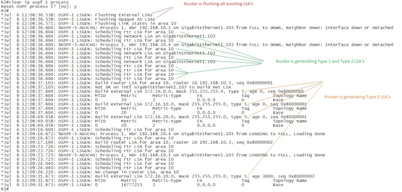
This image is a bit difficult to read, however notice that there are four type 5 LSA's generated by R3. I did say that it would generate three Type 5 LSA's above.
So why is it generating 4?
Long story short, it has to do with OSPF path-selection. It's difficult to see in the picture but the first Type 5 LSA that R3 generates for network 172.16.20.0/24 is with a metric of 20.
The second LSA that it generates for network 172.16.20.0/24 is with a metric of 16777215 indicating that it actually has two paths to reach this network.
So just to be sure of which routes we have, let's also look at the LSA's that R5 generates:

Again we have a couple of Type 5 LSA's that are generated multiple times.
From R5's perspective the following Type 5 LSA's are generated multiple times:
-172.16.10.0/24 (first with a metric of 20, then with a metric of 16777215)
-172.16.0.0/24 (first with a metric of 20, then with a metric of 16777215)
Again we see that the router generates a Type 5 LSA with a high metric, and with a lower metric.
What is interesting with this is that the metric is the same from both R3 and R5. This is because from OSPF's point of view this route is considered to be withdrawn, as in it should not be used anymore so it forces this route out from the OSPF domain by advertising it with a metric that is set to 16777215.
In OSPF terminology, this is called LSInfinity - meaning the route is inaccessable so set the metric to 16777215 (or 0xFFFFFFFF in Hex). The reason is because the maximum metric in OSPF is considered to be 0xFFFFFFFE in Hex or 16777214. So therefor the metric of 16777215 is inaccessable, or what's called LSInfinity (the LSA is Infinity - remove this from the database).
That by itself probably requires a better explanation, but we'll cover that in the Path Selection section. But what we need to know now is what is happening, and why are R3 and R5 generating these Type 5 LSA's.
Here's why R3 and R5 are generating multiple Type 5 LSA's for the same networks:
The short version is that it has to do with the configuration with this topology. More specifically, we are doing redistribution at two points in the OSPF domain and both routers will treat the 172.16.0.0/24 network as external network. But at some point one of the ASBR's are bound to also learn about the 172.16.0.0/24 network via OSPF in which case the OSPF Administrative Distance of 110 will win over the RIP learned route with AD 120. When the OSPF-learned route is installed in the Routing-Table the router that first calculated the SPF will withdraw it's Type 5 LSA since the route is no longer external (it's learned via normal OSPF routing). So the answer is, it generates the Type 5 LSA's and then it's withdrawn but to withdraw the Type 5 LSA it needs to generate a new one with an infinite metric called the LSInfinity value of 16777215.
The long version is that this is a very (extremely) difficult topic to try and explain because what you are experiencing with this topology and configuration is simply put a redistribution problem/issue and not an OSPF issue.
However we have not covered advanced redistribution yet, but this topology is so nice that it generates a lot of advanced situations with OSPF. One of them being this scenario where you would expect both R3 and R5 to generate Type 5 LSA's for network 172.16.0.0/24 but they're not because a redistribution misconfiguration.
Also depending on which ASBR will receive the other ASBR's Type 5 LSA first and run the SPF on the received Type 5 LSA will ultimately decide which router will flush it's own advertised Type 5 LSA.
So if R3 and R5 both sent the Type 5 LSA into the OSPF domain and R5 received R3's Type 5 LSA before R5's Type 5 LSA reached R3 - then R5 will install the R3 external route. That's because the OSPF path-selection will prefer route from R3 with AD 110 over the RIP learned route with AD 120.
In this scenario R5 will believe that it has the worst route, so it will flush it's advertised Type 5 LSA because it will believe that the Inter-area route via R2-R1-R3 is the better route to reach network 172.16.0.0/24.
Note: It's not actually an OSPF Inter-Area route since it will be a E2 - external type 2, however it's an Inter-Area route when looking at the topology.
Amazing, isn't it? That a little redistribute command could cause this trouble ;-). To better understand it let's look at the topology again. This time i've added arrows to indicate the redistributed route path:

As indicated by the Red and Green "arrows" each ASBR will inject the network 172.16.0.0/24 into the OSPF domain. OSPF will not treat External or Internal routes with different AD value. So whichever route is converged the fastest through the OSPF-domain will be installed at the other ASBR.
When that happens, that ASBR will flush it's own Type 5 LSA that was generated and you are left with suboptimal routing because of how a Cisco router chooses the best Path from multiple routing sources.
The key to understanding this is that some parts of the network will converge more quickly than other parts of the network, so the first time the router generates the Type 5 LSA's it will build that Type 5 LSA because it is the best available path decided on the SPF-calculations.
Then at a later stage it will receive new information, calculate the SPF-again for that prefix and then decide that the current advertised Type 5 LSA is not the best so it will flag this as an "inaccessable" network in OSPF terminology. Or make the LSA "Infinite" (LSInfinity) by making the metric too high (simular to how EIGRP and RIP poisons a network to be removed).
Cathing this one would be difficult all by itself, but there is a few debug commands available to catch this in action. Luckily for us, i've already prepared all routers and captured the debug to show you what happens. So to break it down exactly, this is what happens:
First enable some more debug commands on R3 and R5:
debug ip ospf 1 spf external
Looking at R5 first. R5 will look in it's Link-State database, and since it is connected to the 172.16.20.0/24 network it should generate a Type 5 LSA for this network based on OSPF rules:

Sure enough, R5 generates a Type 5 LSA for network 172.16.20.0/24.
This is it's local connected prefix between R5 and R7.
Simular R3 will do the same for it's local connected prefix of 172.16.10.0/24 betwen R3 and R6:

Sure enough, R3 generates a Type 5 LSA for network 172.16.10.0/24.
This is it's local connected prefix between R3 and R6.
Then before any Type 5 LSA is received from inside the OSPF domain (forwarded by either R1 into Area 10 or R2 into area 10) both R3 and R5 should generate a Type 5 LSA for network 172.16.0.0/24 since it's an external network from the point of view of both R5 and 3 at this point.
R5 output:

For this discussion it's worth noting that this Type 5 LSA was generated at 12:54:42.
R3 output:

For this discussion it's worth noting that this Type 5 LSA was generated at 12:54:17.
Note: Both routers indeed generated the Type 5 LSA for network 172.16.0.0/24, but what is interesting is that R3 generated it's Type 5 LSA before R5 generated the same prefix Type 5 LSA.
Looking at the debug output we can tell that R3 advertised about the network 172.16.0.0/24 via a Type 5 before R5 generated another Type 5 LSA for this prefix. What that really means is that we could expect the R3 type 5 LSA to reach the ASBR R5 sooner than the R5 Type 5 LSA reaches the R3 ASBR.
In much easier terminology - R3 won, it's Type 5 LSA will be flooded across the OSPF domain sooner than the R5 Type 5 LSA. Meaning that we could expect R5 to learn about this network (172.16.0.0/24) via the OSPF domain with AD 110. So R5 should withdraw it's Type 5 LSA for that network using a metric of 16777215.
So depending on which router was first to spread the Type 5 LSA for network 172.16.0.0/24 the following will be seen, in this case it was R3. So we would have to look at the output in R5 to see the actual withdrawal process:

Difficult to read, but it does say that it received some external routes, as we can see from the output the ADV Router was 192.1668.10.3. This output tells us that we did receive external routes and that the SPF will be made on these routes. Specifically we received these Type 5 LSA's from R3 (Router ID 192.168.10.3):
-172.16.0.0/24
-172.16.10.0/24
-172.16.20.0/24
All three routes were installed in R5's Routing Table as can be told by the "Route update succeeded for x.x.x.x/255.255.255.0 next-hop yyy" output.
Note: Ignore the fact that R5 took the route for network 172.16.20.0/24 and installed this in it's routing table. It only has to do with that R5 has not computed the metric for it's own link yet.
At this point we know that the Type 5 LSA's from R3 actually reached the R5 ASBR, so let's see if R5 withdraws some of it's previously generated Type 5 LSA's by using the LSInfinity metric. The following can be seen on R5:

Just as we were expecting it to behave. It now have the routes for networks 172.16.10.0/24 and 172.16.0.0/24 installed in the routing table through OSPF AD 110, not via RIP. So it knows it generated Type 5 LSA's for these networks before, so it will flush them by setting the metric to 16777215 so the other routers will know it no longer is the ASBR for these networks.
So if everything worked as planned, R5 should have some routes learned via OSPF and not RIP. Let's verify quickly before proceeding:
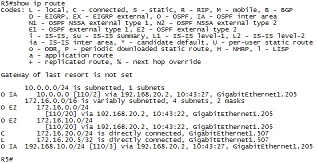
Indeed, isn't that beautiful? R5 have only OSPF routes and no RIP-routes and it chooses the path over R3 to route towards 172.16.0.0/24 and 172.16.10.0/24.
OSPF Design note: This means that since R5 withdraw the Type 5 LSA for network 172.16.0.0/24 it means that R3 will not learn about this network as an external network to OSPF. So from R3's perspective it will route correctly over the RIP-network to reach this network.
Verification that R3 doesn't route suboptimal for network 172.16.0.0/24:

Just as expected, R3 does not learn the OSPF route for network 172.16.0.0/24 but instead routes it directly over to R6 using the RIP-learned network. This is because from R3's perspective it does not learn about any OSPF route for network 172.16.0.0/24, so it's not installed in the routing table. Instead it learns about htis network via the RIP-domain as normal.
Phew. That was a long version to explain how it happens ;-).
Now let us just look at the topology we were using again:
In our example above, R3 was faster than R5 to advertise it's Type 5 LSA's so based on that we should expect the routers to route traffic this way:
R3:
-Will route towards 172.16.0.0/24 over RIP domain.
-Will route towards 172.16.10.0/24 over the RIP domain.
-Will route towards 172.16.20.0/24 over OSPF. (Because R5 generated a type 5 LSA for this network. OSPF has lower AD 110 than RIP 120.)
R1:
-Will route towards 172.16.0.0/24 over R3.
-Will route towards 172.16.10.0/24 over R3.
-Will route towards 172.16.20.0/24 over R2.
R2:
-Will route towards 172.16.0.0/24 over R3.
-Will route towards 172.16.10.0/24 over R3.
-Will route towards 172.16.20.0/24 over R5.
R5:
-Will route towards 172.16.0.0/24 over R3.
-Will route towards 172.16.10.0/24 over OSPF/R3.
-Will route towards172.16.20.0/24 over the RIP domain.
Note about routing decisions: Maybe difficult to spot, but in case you didn't notice. R1 and R2 will route towards it's local ASBR for their directly connected networks. Those are 172.16.10.0/24 on R3 and 172.16.20.0/24 on R5.
This is because another thing we havent discussed yet, it's called the Forwarding Metric which is also part of the Type 5 LSA. This special metric is used in this topology when the same network is advertised by multiple ASBR's.
Networks 172.16.10.0/24 and 172.16.20.0/24 are generated by both ASBRs, since one is known by RIP and the other is directly connected before redistribution. Along with the Type 5 LSA is a value called the "Forwarding Metric".
Basically what it does is to determine which route to choose from in this special case when it will learn about the same prefix from multiple ASBR's.
From R1 and R2's perspective they need to decide which route to install in the routing-table. They will do so by looking at the forwarding metric for these prefixes that they receive from multiple sources. That will be 172.16.10.0/24 and 172.16.20.0/24.
The forwarding metric is the actual metric to reach the ASBR that advertised the prefix. So from R2's perspective the metric for network 172.16.20.0/24 will be lower over R5 than it is going over R3. So it will choose that route.
Vice versa, at R1 the metric to reach 172.16.10.0/24 will be lower through R3 than it will through R5 so it will choose to install the route towards R3.
This can be verified using the command "show ip route 172.16.10.0 255.255.255.0" for example on R1:

Notice that for each route OSPF also learns the forwarding metric. As expected the forwarding metric is higher to reach 172.16.20.0/24 than it is to reach 172.16.10.0/24.
The simular output will be seen on R2.
My point with that was just to demonstrate that R1 and R2 had to choose which route to install for each of the networks. It had multiple sources and it wasn't crystal clear which ones would be installed in the routing table.
As the final verification process, let's look at which Type 5 LSA's are available on all the routers - hopeuflly it will all add up
R1:
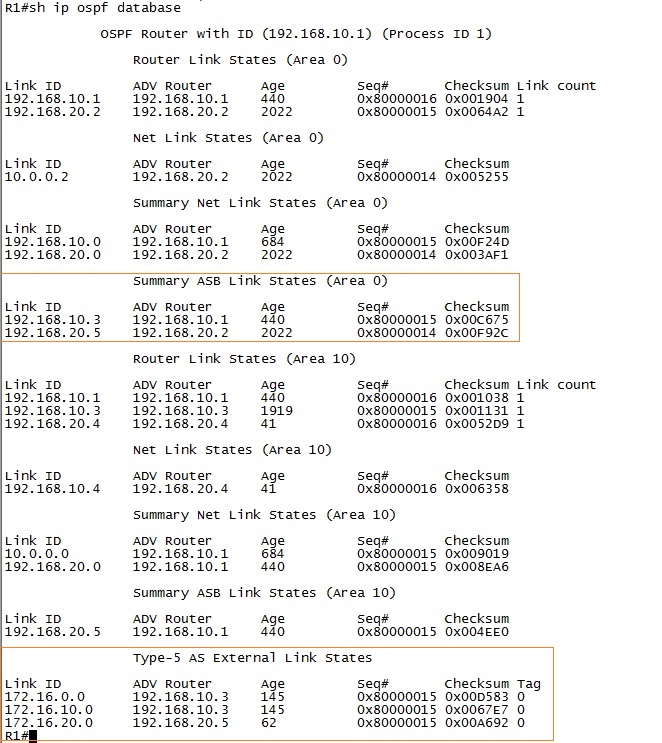
Note: The Type 5 LSA is not area specific, the router either knows about it or it doesn't. However note that the Type 4 LSA is area-specific!
R2:
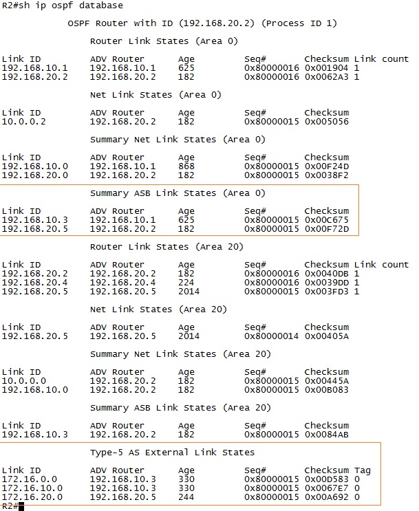
R3:

R5:
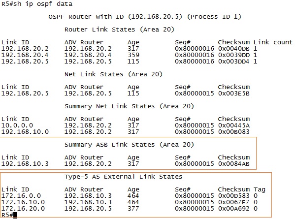
It all added up. Which is great
That concludes the discussion about the Type 5 LSA's. But we still have a problem to fix in case we want to use the topology properly and fix the suboptimal routing.
How is it possible to fix the suboptimal routing and make both R3 and R5 generate Type 5 LSA's properly?
In this topology it's actually pretty easy, all we would have to do is do some sort of filtering so that the networks that are advertised into the OSPF domain are not learned by OSPF on the ASBR networks.
We would just have to put a route-tag when doing the redistribution, and then filter the routes out at the other ASBR. That should effectively block either of the ASBR to learn the external prefixes from any other sources than the RIP-network.
Since the local connected networks are routed correctly, we'll just filter the network 172.16.0.0/24.
1. First we need to capture the networks. I think that's easiest to do with a prefix-list so at both R3 and R5:
ip prefix-list FILTER_EXTERNAL seq 5 permit 172.16.0.0/16
2. Next we need to create a route-map that will link to this prefix-list, the purpose is to set a route-tag for this network and leave every other network unchanged.
R3:
route-map SET_TAG permit 10
match ip address prefix-list FILTER_EXTERNAL
set tag 192.168.10.3
route-map SET_TAG permit 20
R5:
route-map SET_TAG permit 10
match ip address prefix-list FILTER_EXTERNAL
set tag 192.168.20.5
route-map SET_TAG permit 20
3. Then we have to apply this tag to the routes being redistributed into the OSPF domain. So we need to do these changes at both R3 and R5:
router ospf 1
redistribute rip subnets route-map SET_TAG
4. Now the last thing we need to do is to apply the actual filter in the OSFPF process.
R3:
route-map FILTER_ASBR_R5 deny 10
match tag 192.168.20.5
exit
route-map FILTER_ASBR_R5 permit 20
end
configure terminal
router ospf 1
distribute-list route-map FILTER_ASBR_R5 in
R5:
route-map FILTER_ASBR_R3 deny 10
match tag 192.168.10.3
exit
route-map FILTER_ASBR_R3 permit 20
end
configure terminal
router ospf 1
distribute-list route-map FILTER_ASBR_R3 in
Now all routes should be routing the "best" way or the closest way.
Looking at the topology again, R2 will route through R5 and R1 will route through R3 because that's the shortest path now that R1 and R2 receives both Type 5 LSA's.
The effect of the redistribution-filter will be that both routers generate all Type 5 LSA's for all their external networks. So we should see 6 Type 5 LSA's in all routers. Here's the output from R1 and R5 to verify this:


Yes! It's working just like expected
daniel.larsson- Admin
- Posts : 47
Join date : 2015-04-30
Age : 41
Location : Boras, Sweden -
Layer 3 - Open Shortest Path First PART 8
![]() by daniel.larsson Sun Sep 06, 2015 4:12 pm
by daniel.larsson Sun Sep 06, 2015 4:12 pm
Technology:
- OSPF LSA Type 6
- OSPF LSA Type 7
Open Shortest Path First PART 8
(OSPF LSA Type 6,7)
Notes Before Reading: This part will continue to go through how OSPF will work outside it's own network. This part will cover one special LSA-type that will make an external network transit through a part of an OSPF-network where it's usually not allowed to exist. In other words, how OSPF will treat networks that are in a different routing-domain, such as RIP or ISP-redistributed networks - in the special "Not So Stubby Area" area type.
In the previous part we covered the LSA type 5, which contains information about external networks. In this section we move on with the discussion of how you can redistribute an external network, such as RIP or EIGRP, into the OSPF-domain even though you may want to block every other LSA-type external to that area. That's where LSA Type 7 comes into play, it will allow you to inject an external network - as a Type 7 LSA rather than a Type 5 LSA - to later be convered into a normal Type 5 LSA.
This LSA-type can be difficult to understand how it works since it's basically a Type 5 LSA except it's allowed to exist in a "Not So Stubby Area" - in other words, we are allowing external LSA's inside an area where it shouldn't be allowed to exists ... but only as a transit LSA-type until it reaches the ABR that converts it back to a Type 5 LSA for the rest of the network.
That means that to follow the discussion here you need to have a strong understanding of how OSPF works in a multi-area design with external networks redistributed. In other words - a complete understanding of LSA-types 1,2,3,4,5.
This topic is both covered in the CCNP ROUTE books and the CCIE RSv5 official certification guide. For Type 7 LSA's i believe both books cover it well, but neither of them covers the depth required to fully understand how it works. It all depends on how quickly you understand the different OSPF area types.
LSA type 7 is covered, but IMO not enough to get CCIE-level of understanding. So for this part you would therefor have to look into some CCIE-studies (like blogs) or the CCIE RSv5 Official Certification Guide book. It does a very good job at explaining how this works.
If it's not already crystal clear I will repeat myself.
OSPF is a very complex protocol and a very difficult one to master. Even if I consider myself very skilled at OSPF I think I will run into many situations here that are new. Many of the new topics are considered network optimization topics that requires a solid understanding of how OSPF actually work behind the scenes before going into that area.
OSPF LSA Type 6,7
1. Here I would say that you are going to have to read from several sources to understand the Type 7 LSA. Although the CCNP Route book and the CCIE RSv5 book combined makes a good coverage on this LSA-type it's still not enough. The problem is the same as before, lack of content in regards to how it's all working behind the scenes.
Also the same for LSA-type 7 is that the RFC also explains how it works and as we already know, Cisco redefines what the ABR is and does so beware of that when reading the official OSPF RFC! It doesn't affect the ASBR/Type 4 LSA's, however since the ASBR might also be the ABR you would want to look into the RFC and understand what cisco changed to the ABR behaviour.
I will try and really tear apart and show you exactly how the Type 7 LSA work here so there shouldn't be any need to look elsewhere, but if you are interested - the RFC is always a good place to look. Cisco also has a lot of good documentation about OSPF.
So let's move on to do a complete demonstration about what the Type 7 LSA is and how it works. It will be complicated, so be warned!
Book: CCIE RSv5 Official Certification Guide, Chapter 9.
Chapter 8 is named: OSPF.
Note: It's also possible that you may want to read some RFC's about OSPF and some other sites explaining what the LSA Type 7 actually do. Beware though, many many places simplify what is happening. And for CCIE it's required to have a solid understanding, not just a bit about how it works.
IP Routing - OSPF Configuration Guide Link: http://www.cisco.com/c/en/us/td/docs/ios-xml/ios/iproute_ospf/configuration/15-mt/iro-15-mt-book.html
Note: There is just so, so much to read about OSPF so there's no good and accurate configuration guides to point towards. Since almost every single topic of OSPF has it's own configuration guide, like LSA 1, LSA2, LSA3 etc.
Learned:
-That there's too much information about OSPF to actually be able to learn any topics from the configuration guides. However they're well worth a read-through to see how Cisco implements OSPF compared to the RFC-standard. Which we will see - they make a few changes along the way.
OSPF LSA Type 6
LSA Type 6 - Multicast OSPF LSA
This LSA type is not in used, but a very short discussion about it is included just in case. The Type 6 LSA was reserved for a protocol that was called Multicast OSPF or simply MOSPF. Very few routers supported it, and when OSPFv3 came out (with IPv6 support) it got withdrawn. So there is no networks currently in use that uses the Type 6 LSA's because no routers support Multicast OSPF. If you need that kind of networ, you go with IPv6 and OSPFv3 instead!
OSPF LSA Type 7
LSA Type 7 - Not-so-stubby-area LSA
This is called "The Not-so-stubby-area External LSA" and the purpose of the LSA Type 7 is to tell the OSPF domain where External routes are located that exists outside the OSPF domain/topology. This LSA-type is allowed to exist in a "not-so-stubby-area" which is why it's called the "Not-so-stubby-area LSA".
Doesn't that sound the same as for the Type 5 LSA?
Well, yes it does almost the same thing. The difference is that it will be injected as a Type 7 LSA by the ASBR, then at the ABR inside that area it will be convered to a Type 5 LSA and flooded to the rest of the OSPF domain. So it will just be a Type 7 LSA inside the same area where the ASBR is advertising this LSA.
To understand what it really is and how it actually works, a short discussion about different OSPF areas is needed. We will not dig deep at this point since i will dedicate a complete section to these areas. Like EIGRP, OSPF uses different type of areas that you can use to reduce the resource requirements for OSPF and to do some traffic engineering.
Note: There are a few other areas other than Totally-stubby-areas and Not-so-stubby-areas, however that will be covered in another section.
The purpose by using the different OSPF-areas is to reduce the number of LSA's that exists in the area. It does that by using the concept of not allowing some sort of LSA's to exist in that area, instead replacing it with a default route pointing towards either the ASBR or the ABR.
The Not-so-stubby-area is specifically designed to only allow Type 1 and Type 2 LSA's and block Type 3, Type 4 and Type 5 LSA's and replace them with a default route instead - really optimizing the OSPF link-state database since the traffic would be routed the same way even with all those LSA's inside the area.
The Not-so-stubby-area is an implementation of the Totally-stubby-area to allow at least External networks to be redistributed into the OSPF domain using a special Type 7 LSA.
Because with a Totally-stubby-area (blocking type 3,4,5,7 LSA's) no external networks would be allowed inside that area - and per design you would not be able to redistribute the RIP-networks or any other external networks into the OSPF domain because the area type would not allow it.
So that's why we use the Not-so-stubby-area type to be allowed to inject what's called a Type 7 LSA that will be converted to a normal Type 5 LSA in the rest of the OSPF-domain.
What does the Not-so-stubby-area do exactly?
This area type will allow a special sort of Type 5 LSA called the Type 7 LSA to exist in that area. In a Normal Totally-stubby-area we would not be allowed to use anything but Type 1 and Type 2 LSA's. But the information that the Type 7 LSA carries is almost identical to a Type 5 LSA.
Important study note: We will cover the different Area-types after we have discussed how OSPF actually works in a multi-area topology. I believe it's easier to first really understand how OSPF works, and then move into the various featurese available to optimise the network. The NSSA and the Totally Stubby Areas are just a few of those features available.
There are a couple of simular behaviours to Type 7 LSA's as there is to Type 5 LSA's, they're both external and they have the purpose of telling the rest of the network where the ASBR's external network is located.
Having already defined and discussed how the ASBR is defined and identified in the Type 4 LSA section, we can proceed and look at the topology with the RIP-domain again. One important thing to consider when talking about Type 7 LSA's are that - no Type 7 LSA's will be generated as long as you are not injecting any external routes into the OSPF Domain.
To inject external routes it's therefor a requirement to use redistribution to generate Type 7 LSA's. Type 1-3 LSA's are created to map the topology internal to the OSPF domain, whereas Type 4-5 and 7 are used to map the topology external to the OSPF domain.
So without having any kind of external networks to route towards, we can't generate any Type 7 LSA's. The problem with understanding what the Type 7 LSA actually does is that it has a few traffic engineering fields that are not commonly used, but sure enough needs to be covered for CCIE studies.
So let's have a look at what type of information you can expect to see in the Type 7 LSA. Here's the LSA header:
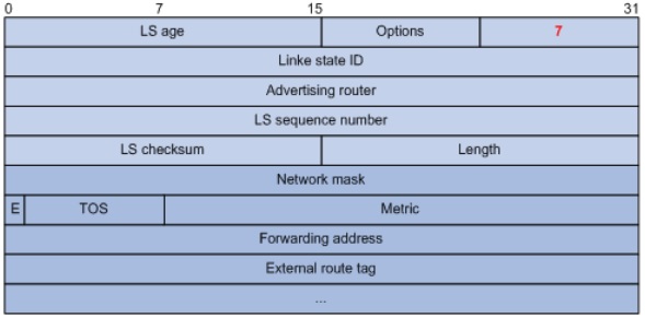
It looks exactly like the Type 5 LSA so i will not in detail go over how that works, if you are curious just look at the Type 5 LSA section because this LSA-type will work exactly the same - the only difference is that it's allowed to EXIST inside the NSSA-area.
Important information to understand about Type 7 LSA and the Forwarding Address Field:
But one small thing we need to cover from the Type 7 LSA header is how it handles the Forwarding Address field - or simply put the FA-field.
Remember that with a Type 5 LSA there are a lot of rules that needs to be met before the FA-field can be used. From a traffic engineering standpoint, it's very difficult to use it as a way to control how to route your traffic since it's very rare that you will be able to meet the requirements to set this field to any other value than 0.0.0.0 - which just means route traffic towards the ASBR.
This changes with a Type 7 LSA - it's mandatory with a Type 7 LSA. So if we were to look at the type 7 LSA vs the Type 5 LSA we would see that it should say 192.168.10.3 in the Type 7 LSA. That is because R3 is the ASBR for the NSSA area and it will generate the Type 7 LSA's.
The Type 7 LSA is later translated into a normal Type 5 LSA at the ABR of the NSSA area. In our topology it will be R1. One interesting thing to note from this translation is the fact that a Type 5 LSA normally would not contain the Forwarding Address with any other value than 0.0.0.0, but in case it was a Type 7 - to - Type 5 LSA translation it will keep the Forwarding Address field intact.
And here is the reason why!
Look at the topology again, this time with Area 10 converted into the NSSA-area:

In our topology, R2, R4 (area 20) and R5 does not know any informaiton at all about the NSSA-area. And since there is a Type 7 - to - Type 5 translation done by R1, from R5's perspective R1 looks like the ASBR. Thats what we use the Forwarding Address field for.
So when R5 needs to forward traffic towards R3 for the external prefixes, it will look at the Forwarding Address field and find which ip-address to route towards. Normaly it would most likely look at the Type 4 LSA to find the path towards the ASBR. However we don't want to route traffic towards R1 (which would be the case if we looked at the Type 4 LSA). We need to route the traffic towards R3 so we route to the Forwarding Address.
Interesting facts here though, are that the router looking at the Forwarding Address would still need to know about the network 192.168.10.0/24 to be able to use that field. And in this case it's not a problem because R5 should have an inter-area route towards that network so it could route directly towards the ASBR that set the FA-field to 192.168.10.3.
Important OSPF configuragion/Design Note: This topology doesn't really support a good use of the FA-field, because with the filter applied that we setup to not cause suboptimal routing in the Type 5 LSA-section will cause R5 to learn about network 172.16.0.0/24 through the RIP-domain.
To make R5 actually go the long way around and route traffic towards R3 we would need to delete this filter. That will cause R5 to actually use the FA-field of the Type 5 LSA that R1 generated.
But, i've already taken care of that with the config we did. Because we only applied the filter on network 172.16.0.0/24 which means that network 172.16.10.0/24 will be allowed to reach R5 as a Type 5 LSA so it will learn this route via OSPF instead of the RIP.
Traffic Engineering Note: With the redistribution and filtering in the topology, and by using the NSSA-area we are not causing suboptimal routing from R3 becuase it would not see the Type 5 LSA's that R5 generated for the 172.16.20.0/24 network. In other words, we have traffic engineered the network from R3's perspective to use the RIP-domain to reach the RIP-networks. And only because we made that area NSSA!
If it wasn't crystal clear already - to generate a Type 7 LSA we need to create a Not-so-stubby-area in our OSPF-topology. For this discussion, I will take Area 10 and make it the NSSA-area. It's a simple command that you need to enable on all routers or the OSPF adjacencies will fail:
R1:
router ospf 1
area 10 nssa no-summary
R3:
router ospf 1
area 10 nssa no-summary
R4:
router ospf 1
area 10 nssa no-summary
Note: This will force all adjacencies to go up and down, so use this in a production environment with caution. That's because the area type changed, so they will have to agree on the neighbor rules again and the Area type is one of those rules to check.
The topology now look like this:
Topology note: It does say that Area 10 is NSSA, just not specifically a Totally not-so-stubby area that i configured it as. I just don't want any other routes in that area than the default route towards R1 - which is why i add the no-summary in the config. The command "area 10 nssa" would have been a perfectly valid implementation/configuration given the topology requirements!
The topology is the same, but we have changed area 10 into NSSA meaning we do not allow any Type 3,4,5 LSA's inside that area except for a default-route pointing towards the ABR.
Much of this discussion will have the same issues that we discussed in the Type 5 LSA section, so i will not repeat those issues. But to prevent them from happening, the redistribution is still applied on both R3 and R5. However in this case it's not needed in R3 because it will never receive any External LSA's from R5 since the NSSA-area block it.
Note about Cisco implementation of OSPF: Remember that Cisco's implementation of OSPF does not treat R4 as an ABR, but just a link in both areas that it has interfaces configured for.
Since we're talking about Type 7 LSA's in this section i will just keep it to explain how Type 7 LSA's work and ignore the Type 2/3/4 LSA's also generated.
Based on the above topology the following LSA's would be generated (we're looking into Type 7 LSA's, however a Type 4 LSA is needed to find the ASBR that originated the Type 7 LSA....the Type 4 in return requires Type 1 LSA's to tell if it should generate Type 4 LSA's):
R3
-Will generate a Type 1 LSA with Link-State ID of 192.168.10.3 (the ip-address of the link in area 10) with a Advertised Router of 192.168.10.3 (the Router ID of R3).
-Will also set the E-bit in the Type 1 LSA since it's connected to the RIP-domain. This will flag this link as a "AS Boundary Router".
-Will receive a Type 4 LSA from R1 with Link-State ID of 192.168.20.5 and with a Advertised Router of 192.168.10.1
-Will generate a Type 7 LSA with Link-State ID of 172.16.10.0(the network address of the external network), with a Advertised Router of 192.168.10.3 (the Router ID of R3), with a Metric Type 2 External, with the Forwarding Address field set to 192.168.10.3 (it will use the outgoing interface ip-address that is used to advertise the LSA)
-Will generate a Type 7 LSA with Link-State ID of 172.16.20.0(the network address of the external network), with a Advertised Router of 192.168.10.3 (the Router ID of R3), with a Metric Type 2 External, with the Forwarding Address field set to 0.0.0.0 (it will use the outgoing interface ip-address that is used to advertise the LSA)
-Will generate a Type 7 LSA with Link-State ID of 172.16.0.0(the network address of the external network), with a Advertised Router of 192.168.10.3 (the Router ID of R3), with a Metric Type 2 External, with the Forwarding Address field set to 0.0.0.0 (it will use the outgoing interface ip-address that is used to advertise the LSA)
-Will not receive any Type 5 LSA's since the area is NSSA.
R5
-Will generate a Type 1 LSA with Link-State ID of 192.168.20.5 (the ip-address of the link in area 20) with a Advertised Router of 192.168.20.5 (the Router ID of R5).
-Will also set the E-bit in the Type 1 LSA since it's connected to the RIP-domain. This will flag this link as a "AS Boundary Router".
-Will generate a Type 5 LSA with Link-State ID of 172.16.10.0 (the network address of the external network), with a Advertised Router of 192.168.20.5 (the Router ID of R5), with a Metric Type 2 External, with the Forwarding Address field set to 0.0.0.0 (since it doesn't apply to the rules required to set this field to any other value than 0.0.0.0)
-Will generate a Type 5 LSA with Link-State ID of 172.16.20.0 (the network address of the external network), with a Advertised Router of 192.168.20.5 (the Router ID of R5), with a Metric Type 2 External, with the Forwarding Address field set to 0.0.0.0 (since it doesn't apply to the rules required to set this field to any other value than 0.0.0.0)
-Will generate a Type 5 LSA with Link-State ID of 172.16.0.0 (the network address of the external network), with a Advertised Router of 192.168.20.5 (the Router ID of R5), with a Metric Type 2 External, with the Forwarding Address field set to 0.0.0.0 (since it doesn't apply to the rules required to set this field to any other value than 0.0.0.0)
-Will receive Type 5 LSA's that R1 generated but with the FA-field set to 192.168.10.3.
R1
-Will generate and advertise Type 4 LSA's into Area 0 with Link-State ID of 192.168.10.3 and with the Advertised Router of 192.168.10.1
-Will receive Type 4 LSA's from R2 but it will not flood this into Area 10. This will have a Link-State ID of 192.168.20.5 and with the Advertised Router of 192.168.20.2. (it will not flood it into Area 10 because it's a NSSA-area which doesn't allow Type 4 LSA's)
-Will receive the Type 7 LSA's from R3 and convert these into Type 5 LSA's and flood them into Area 0.
-Will convert a Type 7 LSA to Type 5 LSA with Link-State ID of 172.16.10.0(the network address of the external network), with a Advertised Router of 192.168.10.1 (the Router ID of R1), with a Metric Type 2 External, with the Forwarding Address field set to 192.168.10.3 (it will keep the forwarding address that was in the Type 7 LSA)
-Will convert a Type 7 LSA to Type 5 LSA with Link-State ID of 172.16.20.0(the network address of the external network), with a Advertised Router of 192.168.10.1 (the Router ID of R1), with a Metric Type 2 External, with the Forwarding Address field set to 0.0.0.0 (it will keep the forwarding address that was in the Type 7 LSA)
-Will convert a Type 7 LSA to Type 5 LSA with Link-State ID of 172.16.0.0(the network address of the external network), with a Advertised Router of 192.168.10.1 (the Router ID of R1), with a Metric Type 2 External, with the Forwarding Address field set to 0.0.0.0 (it will keep the forwarding address that was in the Type 7 LSA)
R2
-Will generate and advertise Type 4 LSA's into Area 0 with Link-State ID of 192.168.20.5 and with the Advertised Router of 192.168.20.2
-Will receive Type 4 LSA's from R1 and flood this into Area 20. This will have a Link-State ID of 192.168.10.3 and with the Advertised Router of 192.168.10.1.
-Will receive Type 5 LSA's from both R5 and R1.
-Will advertise the received Type 5 LSA's from R5 into Area 0.
-Will advertise the received Type 5 LSA's from R1 into Area 20.
We have already taken care of the redistribution and the suboptimal routing so that R3 and R5 learn about the 172.16.0.0/24 network through RIP and not OSPF. So there's no point in having that discussion again. But what we didn't discuss before is that by not allowing any Type 5 LSA's inside the NSSA area - then R3 would never know about the external networks that R5 generates.
So by doing this we also get rid of the suboptimal routing that R5 now suffers from, since it will learn about network 172.16.10.0/24 through OSPF and route it via OSPF rather than through the RIP-domain. R3 will not have this problem because it never received the Type 5 LSA's that R5 generated. So R3 will route properly, and R5 will have to route-around the OSPF domain for the 172.16.10.0/24 network.
But what is and will be interesting is that we should expect the following based on the OSPF design:
-R3 should not receive or have any Type 5 LSA's, but it should generate at least 3 Type 7 LSA's.
-R1 should have at least 3 Type 7 LSA's in Area 10.
-R1 should convert at least 3 Type 7 LSA's from Area 10 to a Type 5 LSA and advertise these into Area 0 and when doing so keep the Forwarding Address fromt he Type 7 LSA (192.168.10.3)
-R2 should have at least 3 Type 5 LSA's from R5 and at least 3 Type 5 LSA's from R1, and it should not have any Type 7 LSA's since they only exist inside the NSSA-area.
-R5 should therefor have 6 Type 5 LSA's (two for each network). One which it originated itself when it generated it's own Type 5 LSA's and one for each network that points towards R3.
As we have discussed and talked about almost anything that can happen in this topology already, it's not much more to discuss other than have a look at the database and see how it looks like.
Starting with R1:

What is interesting here is that Area 0 only contains the Type 4 LSA from R2 that is generated because R5 flags itself as ASBR.
Looking at Area 10 we can see that it has Type 7 LSA's that R3 generated. But more interestingly, notice that there is a single Type 3 LSA in there which is the default route (0.0.0.0 as Link ID) pointing towards R1.
And we can also see all the Type 5 LSA's that have been generated in the network. Notice that we only have a single LSA for network 172.168.10.0/24 pointing towards R1. That's because R5 did the Type 7 -to- Type 5 LSA conversion for that network - and because R5 learns about this network through OSPF so it's not advertising a Type 5 LSA for it.
For R2 the output will be almost the same:

What is interesting here is that Area 0 only contains the Type 4 LSA from R3 that is generated because R5 flags itself as ASBR. It's also interesting that this router, compared to R1, does not contain any Type 5 LSA's. Instead it received Type 5 LSA's from R1 - since they were converted over at R1 into Type 5 LSA's and flooded into Area 0.
And we can also see all the Type 5 LSA's that have been generated in the network. Notice that we only have a single LSA for network 172.168.10.0/24 pointing towards R1. That's because R5 did the Type 7 -to- Type 5 LSA conversion for that network - and because R5 learns about this network through OSPF so it's not advertising a Type 5 LSA for it.
Over at R5 we should expect a smaller database:

Here is a very interesting thing to discover. Notice that here is where we will see the Type 4 LSA that should be generated over at R1 since it receives a Type 1 LSA from R3 that tells it that R3 is the ASBR.
However since R1 is doing a Type 7 -to- Type 5 conversion for Area 0, it means that when this Type 5 LSA leaves Area 0 the Type 4 LSA is also generated by that router. In this case R2 had to generate it since it advertised about the Type 5 LSA outside Area 0.
Notice that this Type 4 LSA is only located in the area outside of Area 0.
And we can also see all the Type 5 LSA's that have been generated in the network. Notice that we only have a single LSA for network 172.168.10.0/24 pointing towards R1. That's because R5 did the Type 7 -to- Type 5 LSA conversion for that network - and because R5 learns about this network through OSPF so it's not advertising a Type 5 LSA for it.
And over at R3 we should expect an even smaller database since it's a NSSA-area:

Indeed it's a small database. Only the Type 7 LSA's and a single Type 3 LSA exists from external areas. As expected almost all external LSA's are removed from the NSSA-area, except the Type 7 that are allowed to travel through this area type to be converted into a Type 5 LSA at the ABR.
This finally means that we have covered all the OSPF LSA types that are part of the CCIE RSv5 blueprint.
daniel.larsson- Admin
- Posts : 47
Join date : 2015-04-30
Age : 41
Location : Boras, Sweden -
Layer 3 - Open Shortest Path First PART 9
![]() by daniel.larsson Sun Sep 20, 2015 11:54 pm
by daniel.larsson Sun Sep 20, 2015 11:54 pm
Technology
- OSPF Header & Packet Types
- OSPF LSA Update/Withdrawal process
Open Shortest Path First PART 9
(OSPF Header & Packet Types, OSPF LSA Update/Withdrawal process)
Notes Before reading: This part will continue to go through how OSPF will work. But in more detail than before. We will look into exactly how the LSDB is populated and depopulated. In other words, tear OSPF apart and explain exactly what happens behind the scenes.
To understand this part it's required to have a very good knowledge about pretty much everything on how OSPF operate. More specifically you need to fully understand all the LSA-types in depth, and most of the fields that OSPF uses in the various LSA's.
OSPF is a very complex protocol and a very difficult one to master. Even if I consider myself very skilled at OSPF I think I will run into many situations here that are new. Many of the new topics are considered network optimization topics that requires a solid understanding of how OSPF actually work behind the scenes before going into that area.
OSPF Header & Packet Types, OSPF LSA Update/Withdrawal process
1. These topics does not have a very good book at all. The best resource to understand these topics will be the RFC 2328, which defines how OSPF should operate according to the standard. The OSPF-packet types can be covered by the CCIE RSv5 Official certification guide, but it's not enough IMO. It doesn't go deep enough to fully understand the process, that's why i would recommend to look at the RFC first.
I will try my best to really tear apart and show you exactly how the OSPF-process updates the database and withdraws information from the database. But it's some very complex and advanced stuff to discuss unless you fully understand the LSA-type. Just a heads-up warning about it!
So let's move on to do a complete demonstration of the OSPF header, the packet types and the Update/Withdrawal of Link-State Database information!
Book: CCIE RSv5 Official Certification Guide, Chapter 9.
Chapter 8 is named: OSPF.
OSPF RFC 2328 Link: https://www.ietf.org/rfc/rfc2328.txt
Note: The best material to understand this process is the RFC, and I know it can be difficult to read it from time to time. So if you still don't understand it, look at other CCIE blogs to see what they are telling about these topics.
During my studies i found it the most difficult to understand and learn about how the database is populated and depopulated, since there is very little good documentation about it!
IP Routing - OSPF Configuration Guide Link: http://www.cisco.com/c/en/us/td/docs/ios-xml/ios/iproute_ospf/configuration/15-mt/iro-15-mt-book.html
Note: There is just so, so much to read about OSPF so there's no good and accurate configuration guides to point towards. Since almost every single topic of OSPF has it's own configuration guide, like LSA 1, LSA2, LSA3 etc.
Learned:
-That there's too much information about OSPF to actually be able to learn any topics from the configuration guides. However they're well worth a read-through to see how Cisco implements OSPF compared to the RFC-standard. Which we will see - they make a few changes along the way.
OSPF Header & Packet Types
OSPF Packet Types
-When talking about OSPF it's going to be difficult to understand it without also knowing the various OSPF Packet Types that exist. It's not a difficult topic, but it's a topic that I see that not many people decide to learn about.
When we discussed the OSPF LSA-types i showed a couple of pictures mainly containing all the LSA-type headers of interest. If you paid attention to those pictures you would have seen that there were some fields that said "type", "packet length" and also "checksum".
This is called the "Common OSPF Header". It's called that because these are common fields that all the OSPF-packet types will contain. It looks like this:

As you can see in this image we have all those fields:
- -Type
- -Packet Length
- -Checksum
The purpose of the OSPF packet types:
As you already know by now OSPF is a Link-State routing protocol that by design uses a Link-State Database to keep track of various link-states in the topology of the OSPF-domain.
To maintain, store and update information in this database OSPF uses a few different message-types. These are the so called "OSPF Packet Types".
The different OSPF-packet types are:
- 1. Hello packet
- 2. Database Descriptor packet
- 3. Link State Request packet
- 4. Link State Update packet
- 5. Link State Acknowledgment packet
They all serve a different purpose for the OSPF process.
The endgoal is to make sure that the LSDB (Link-State DataBase) contains the correct information. To do so OSPF will use these different OSPF Packet Types depending on the task required.
For example, if a new link is added the OSPF process will flood the Link-State throughout the OSPF domain using various LSA-types available. The LSA-types will be sent using the OSPF Packet Type 2 - or the "Database Descriptor Packet".
This was just an example of how an OSPF-packet type is used.
To explain this as easy as possible it's better to look at an image that explains how the OSPF process uses the packet-types and when they are used:

This image simplifies the process a bit but it's a good start to get used to the whole process of how OSPF thinks when it's working. To understand this process we need to understand the terminology used.
These are the main definitions that we need to understand:
- -LSDB = Link-State DataBase.
- -LSAck = LSA Acknowledgement.
- -Sequence no = Sequence Number.
- -LSage = Link-State Age.
- -LSRefresh = Link-State Refresh Timer.
- -LSA MaxAge = Link-State Max Age timer.
- -LSInfinity = The highest metric allowed for a specific link.
Note: There are a lot of more fields, options and timers that are part of the OSPF-RFC but for now these are the important ones to define.
Link-State DataBase
This is as simple as it sounds and it is the database that every OSPF router will store to run the SPF-algorithm against. This is the database that you can access and view using the various alterations of the command "show ip ospf database <type of lsa to view>".
The database will keep information about the stored LSA-types, their sequence numbers and their age. Yes there is a default maximum age for each LSA-type stored which is 30 minutes.
If the age expires the router will have to re-flood the LSA throughout the entire OSPF-domain with an increased sequence number.
Note: This means that even in the most stable OSPF-network every 30 minute you will have to re-flood all your links with a higher sequence-number.
Link-State Advertisement Acknowledgement
It's not easy to spot when first looking at OSPF, but it uses a concept simular to TCP in that it will acknowledge all the Link-State Advertisements so that the router that flooded them knows it was received.
Sequence number
This just means a number that OSPF uses to tell which LSA-to keep in it's routing table. The LSA with the highest sequence-number contains the most recent link-state information. When the OSPF-process starts it will flood it's LSA's with the sequence number of 0x80000001. If it needs to send an update about that link, for example that it goes down, then it will increase the sequence number to 0x80000002 and so on.
This is how OSPF-ultimately will decide which information is the most correct to store in the Link-State Database.
Note: There is an interesting fact about why it starts at 0x80000001 since it's a 32-bit integer number. It has to do with the most significant bit and how a computer handles positive and negative numbers.
Link-State Age Timer
Every router that generates any type of LSA will use the so called "LSAge" field to keep track of how old that LSA is. The purpose is that when this value reaches 30 minutes it's re-flooded into the OSPF-domain with an increased Sequence-number if the link is still active. If this timer reaches 60 minutes it's considered inactive and is removed from the database. And the router also informs the rest of the OSPF-domain that this route is no longer valid by "flushing" this route.
Basically it's just a counter for how long this LSA was active, each LSA is refreshed every 1800 seconds (30 minutes) and this field helps to keep track of when it needs to be refreshed.
This field is also used to figure out if the link is inactive, in which case it needs to be flushed from the routing table and the other routers must learn that it's inactive - that means it's reached the age of 60 minutes.
Note: Of course if the router detects that a link goes into the DOWN/DOWN state it wil become inactive immediately, but what this timer does is keeping track of how "old" the LSA is that the router generated.
Link-State Refresh Timer
This timer is how often every LSA will be reflooded by all OSPF-routers that originated the LSA. By default this timer is 1800 seconds, or 30 minutes. So this means that every LSA that is active in the topology will be re-flooded every 30 minutes.
The refresh-timer is triggered when the LSage-field reaches 30 minutes.
Note: These LSA's are even flooded in a very stable topology since by design they will be reflooded every 30 minute if the link is still active. It's possible to manually disable this feature since in a stable topology it makes no sense to re-flood all the LSA's and re-do the SPF-calculations every 30 minutes.
Link-State Max Age Timer
This is an industry-standard defined value according to the RFC, which defines that if the "LSage field" reaches 60 minutes the LSA is "flushed" throughout the OSPF-domain and is not part of the routing-table anymore.
This value is compared to the "LSage field" and in case it reaches 60 minutes it's flushed and flooded/withdrawn from the OSPF-domain.
LSInfinity Value
This is a very interesting value to understand. Basically what it does is that it defines what the max-value for the metric for any given link will be. In other words, you can't have a metric higher than this.
That brings us to some interesting design and engineering points. What if the metric for a link exceeds this value? Yep - you guessed it. It becomes unreachable! And this is also how OSPF "withdraws" routes when links goes down, it floods the same LSA-type with the LSInfinity value set to the max-value.
But the problem is that we have two different values to work with, and they have two entirely different meanings.
Note about confusion: Even though it says infinity in it's name, it doesn't mean that it's an "count to infinity value" (like RIP hop-count of 16). It's a confusing name to specify the max-value that you can have as a metric for a specific LSA.
To further add to the confusion, we would have to look at the specific LSA-headers to see how big value we can store in this field. For example, take a look at the Type 1 LSA and the Type 3 LSA header. Do you see a difference?
Type 1 LSA header:
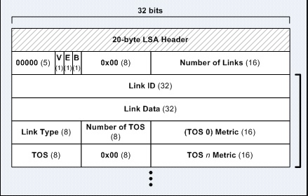
Note: The metric field is 16 bits!
Type 3 LSA header:

Note: The metric field is 24 bits!
Now that is interesting. The OSPF LSA-header defines a different number of bits to represent the "metric" for the Link-type. And that really makes a bit of sense if you think about it.
OSPF is designed this way to help a bit with performance and memory consumption. Since it's likely that the internal area, represented among Type 1-2 LSA's, will contain a "smaller" metric compared to the possible metric value of those links external to the area itself (represented by Type 3-7 LSA's).
Here is the confusing part about these two LSInfinity metric values:
- For Type 3-7 LSA's the maxim metric value is 24-bits fliped to 1, giving a decimal value of 16777215.
- For type 1-2 LSA's the maximum metric value is 16-bits fliped to 1, giving a decimal value of 65535.
And here's how the RFC's explains these values and LSInfinity:
Note: This specifies what it means for Type3-7 LSA's. This does NOT define what it is for Type 1-2 LSA's!From RFC2328 the definition of LSInfinity is (Type 3-7 LSA's): wrote:"The metric value indicating that the destination described by an LSA is unreachable.
Used in summary-LSAs and AS-external-LSAs as an alternative to premature aging (see Section 14.1).
It is defined to be the 24-bit binary value of all ones: 0xffffff."
Note 2: What it also doesn't specify here is that this value can be used to flush a LSA type 3-7 from the OSPF-topology before the LSage field reaches 60 minutes. In other words, if a link can't be used - set that LSA metric value to 16777215 to flush it out from the topology.
From RFC3137 the definition of LSInfinity is (Type1-2 LSA's):
First we would have to take a quote to define what this RFC is trying to accomplish, or we would not be able to understand why the Router LSA maximum metric work differently than the external LSA's.
Here's how the RFC defines the problem if we would make 65535 "unreachable" to OSPF-routers:
From RFC3137 the definition of LSInfinity is (Type1-2 LSA's): wrote:"In some situations, it may be advantageous to inform routers in a network not to use a specific router as a transit point, but still
route to it. Possible situations include the following.
- The router is in a critical condition (for example, has very
high CPU load or does not have enough memory to store all LSAs
or build the routing table).- Graceful introduction and removal of the router to/from the network.
- Other (administrative or traffic engineering) reasons.
"
Clarification what it means: It basically means that sometimes you may need to take "down" a router so that no traffic is in TRANSIT through this router - but you still want it in the topology and you should still be able to manage it. In other words, you don't want to bring it down you just want to avoid routing traffic THROUGH it.
If we would make the max-value 65535 become "unreachable" it would mean the LSA get flushed and removed from the topology and it would no longer be part of the other OSPF-routers SPF-algorithms. In other words, the path would not be calculated.
So what this RFC is saying is that this is a solution to that problem:
Clarification about what it means: It's very difficult to spot in these RFC's but what it really means is that you are allowed to set the metric to 65535 without making that link "unreachable", to address issues like high CPU-load or other things that would make this router undesirable as a transit-router.RFC 2328 wrote:"To address both problems, router X announces its router-LSA to the
neighbors as follows.
costs of all non-stub links (links of the types other than 3)
are set to LSInfinity (16-bit value 0xFFFF, rather than 24-bit
value 0xFFFFFF used in summary and AS-external LSAs)."
This gives us the option of not flushing the LSA-out, but to keep it and still engineer other routers to not transit traffic through this router since the metric for this path is going to be bad.
Key point to understand: Is that we have two different MAX-values for the metric cost for internal vs external LSA's. And it's very important to understand that they have different meanings:
- -For external LSA's it will become unreachable, LSA will be flushed and not visible in the topology.
- -For internal LSA's it will become the highest available metric, so transit traffic is extremely unlikely to transit through this link. The router is still available in the topology.
Last but not least - A very short summary of how these fields work together:
If it wasn't clear already, there are a lot of things going on behind the scenes when using OSPF. The majority of the issues with OSPF is that even in a stable topology the Link-State Types will be reflooded at regular intervals (30 minutes) and every router would have to recalculate the SPF...since they will have a higher Squence-number.
The reason for that is that by default every 30 minutes each router that originated the active LSA will re-flood it, using a higher sequence number will enforce the LSA to be added to the LSDB, triggers an LSA-Ack and forces the SPF-to be recalculated for that LSA.
After 60 minutes it's considered inactive and will be flushed from the routing table and from the OSPF-domain.
Important Note about OSPF design practices: This is why many books and many engineers have trouble scaling OSPF in enterprises and in large topologies. All these reflooding of LSA's can be VERY resource heavy since it's by design. Luckily, it's possible to disable the refresh-timer on a per-interface level.
OSPF LSA Update/Withdrawal process
How the OSPF database is populated with information:
This is going to be difficult to explain easily. But if we look at the process picture again and then compare it with some information that each LSA-type contains we can figure it out.
Basically we have two different scenarios.
1. What happens when a router recieves the LSA?
2. What happens when the router needs to flush the LSA?
So let's first look at the process again to understand how the OSPF router thinks:
The first thing that we can see is that at least one router will send some LSA-type to the rest of the OSPF-routers.
So to continue this discussion let's have a look at the LSA-type 1 for example:

We have already covered what all this information means. But it's still interesting to note down that we have a couple of fields that needs to be checked by the OSPF-router in order to determine what it should do with this LSA.
Namely these fields will be used by OSPF to decide what to do next:
- The "LSage field".
- The "LS sequence number field".
These fields will be checked to determine if the LSA that was received is going to be discarded (not going through the SPF-calculations or become included in the LSDB) or if it's going to be included in the LSDB.
Along with those fields there are a couple of other things that the OSPF-router does to make sure that the packet is valid. For instance the router will calculate the "checksum" value for the LSA and if it matches the "LS checksum field" it's considred to be a valid LSA.
I don't believe they are too important to understand OSPF but if you are curious you should check out the OSPF RFC 2328, which explains this in more detail. (very lengthy document full of boring text IMO!)
What I do belive is important to understand though is that OSPF uses a lot of other fields to operate successfully. Fields that I have not meantioned in this document. Fields that I have never been in need to know how they work, fields that I don't believe is essential to understand even for the CCIE-certification.
So I'm not going to be thorough enough to go through them. And with this information, we can have a look at the OSPF-process again and continue the discussion of what happens when a router receives a LSA:
The steps that any OSPF-router will take when receiving a LSA are the following:
1. It will check if the entry is already in the LSDB or not.
- If it's not in the LSDB then the router will follow the process to populate the LSDB (add it to the LSDB), acknowledge the LSA to the router that originated it, Flood this LSA to the rest of the OSPF routers, Run the SPF on the LSA and in the end calculate a new routing-table if needed.
2. If it's already in the LSDB it will check the sequence number to decide whether or not it should be ignored.
- If the sequence number value is higher then the router will proceed to step 1 and populate the LSDB with this LSA that is newer than the one currently stored in the LSDB.
- If the sequence number value is lower then the router will proceed to send a Link-State Update packet towards the source-router so it will learn about a better LSA. And it will of course keep the current LSA in the LSDB.
- If the sequence number value is exactly the same then the router will proceed to ignore the LSA.
That's all there is to know how the router will decide what to do with received LSA's from other routers.
During my studies things like these are difficult to remember, and what worked for me is to just remember that it will check the sequence number to decide what to do with received LSA's.
The different OSPF-packets that helps maintain and populate the LSDB information
This is very important information to know and understand. The reason for that is because typically when discussing OSPF we will talk about different LSA-types and OSPF-packet types and the meaning of them.
We rarely talk about the process described above because that's pretty much a CCIE-and-beyond topic only!
With the LSDB-process completed we will now move into explain how OSPF uses the various packets that help in the process explained above. In the following order we will cover:
- 1. Hello packet (Type 1)
- 2. Database Descriptor packet (Type 2)
- 3. Link State Request packet (Type 3)
- 4. Link State Update packet (Type 4)
- 5. Link State Acknowledgment packet (Type 5)
To understand the different packet types it's important to understand that they all belong to the same standard OSPF-header which then may contain LSA-headers. So let's look at the OSFP-header again:

Note that there is a Type field which will mark what type of OSPF-packet will be sent.
Now that we know that they will all be using the same OSPF-header we can proceed and try to understand the purpose of the different packet-types.
1. OSPF Packet Type 1 - The OSPF Hello Packet.
This packet-type is the packet that OSPF-uses to periodically maintain neighbor relationships on every link that OSPF-is running on. When I say that, it may sound easy. But it's difficult to explain in an easy way.
This packet will:
- -Be used to form neighbors out every OSPF-enabled link.
- -Will be used to maintain neighborship relationships out every OSPF-enabled link.
- -Will be used to elect the DR/BDR on Broadcast and NBMA networks.
- -Will be using multicast address 224.0.0.5 (all OSPF-routers) on all interfaces except virtual-links where it will use unicast.
If we take a look at how this packet look like it's easy to understand why it's used for these processes:

Note: This image indicates that there is the standard OSPF-header first. But what you can't see here is that the OSPF-header would contain a "1" in the "type" field for the OSPF-header - since this is a hello-packet.
It doesn't become much clearer than this. It will contain every information needed to form a relationship with a neighbor and maintain that information. We haven't discussed the DR/BDR process yet but that's what the "Rtr Prio" field is used for.
I will list a complete definition of what all the fields are used for in this list:
Network Mask - This whill be the subnetmask of the link from the advertising OSPF-router. For unnumbered point-to-point interfaces and virtual-links this will be set to 0.0.0.0.
Hello Interval - This will contain the information of how often the hello-packets are advertised of the link from the advertising OSPF-router. By default this is 10 seconds for Point-to-Point links and 30 seconds for NBMA/Broadcast links.
Options - The advertising OSPF-router can set special options for the link it's advertising by using this field.
Rtr Prio - This is the priority of the advertising OSPF-router. This is used for the DR/BDR election process on any shared-network, such as Ethernet. If this value is set to "0" the router does not participate in the election process - or disabled to participate in the process.
Router Dead Interval - This is Dead Interval Timer that the advertising OSPF-router is using on this link. By default it's 40 seconds for Point-to-Point links and 120 Seconds for Broadcast/NBMA networks.
Designated Router - This is the IP-address of the current Designated Router on that segment/link known by the advertising OSPF-router. If there are no DR elected, then this value is going to be 0.0.0.0.
Backup Designated Router - This is the IP-address of the current Backup Designated Router on that segment/link known by the advertising OSPF-router. If there are no BDR elected, then this value is going to be 0.0.0.0.
Neighbor - This field is tricky! It's going to hold information about all the routers on that link from which the advertising OSPF-router have received a valid hello-packet. And it will contain the Router-ID from all those routers that are sending valid hello-packets on that link.
That's basically all there is to the hello-packet type. As I said in the beginning, the only use of this packet is to maintain neighbor-relationships and elect DR/BDR's on that segment.
Very Important thing to understand: If the routers does not agree on the parameters contained inside the hello-packet, then the router will not send any other OSPF-packet types either.
In other words, if the hello-packets are NOT valid on the link - it will not speak with the other OSPF-router anymore on that link!
2. The OSPF Database Descriptor Packet - OSPF Packet Type 2.
This packet type will be used to describe the contents of the current Link-State Database that the router producing this packet is having. The packet is used to synchronize the database between OSPF-enabled routers.
All routers start sending these packets when any adjacency is formed between two OSPF-enabled routers. It's a very important step in the process because the DBD-packets contain all LSA's that the advertising router knows about.
This packet will:
- -Synchronize the LSDB among all OSPF-routers in the OSPF-domain.
The idea with this packet is therefor to inform other neighbors about what LSA's they know about. And that process is basically two steps:
- 1. First the router produces the LSDBD-packet and send it to the neighbor once the adjacency is formed.
- 2. The receiving router will look at the DBD-packet and check all the LSA's it contains. If any new LSA's are found, it will request this LSA from the advertising router by sending a LSA-Request-packet back to it.
Note: Step 2 in that proces also includes any check to verify that the most recent LSA is valid in it's own LSDB. So if the LSDBD-packet contains information about any LSA already known to the local router, but with a higher sequence-number - it will also request this LSA from the advertising router since it will assume it have a better look of the topology.
How the DBD-exchange process works:
Of course I simplified it with the above explanation just to get us started. There is not much happening in the background, but a few things needs to be considered. Depending on the size of your network, the LSDB will be either small, medium, large or huge. This means that it may be possible that a router sending DBD-packets would not be able to send all the required LSA's in a single packet.
Also remember that I said that when the router becomes adjacent with another router, it will start sending these DBD-packets. And since it requires two routers to form the adjacency, both can't send their DBD-packets at free will. There are rules to follow!
That brings us to discuss som interesting things that OSPF needs to be able to handle:
- -It must be able to handle multiple DBD-packets and be able to tell in which order they should be looked at.
- -When two routers become neighbors and have formed a full adjacency, they must figure out who will send their DBD-packets first. This is done by electing a Master/Slave router during this process.
To understand how this works, it's best to first have a look at how the DBD-packet format look like:

Note: This image indicates that there is the standard OSPF-header first. But what you can't see here is that the OSPF-header would contain a "2" in the "type" field for the OSPF-header - since this is a Database Description Packet.
There are a couple of fields here that needs some more explanations. So I will list a complete definition of what all the fields are used for in this list:
Interface MTU - Will list the MTU-value of the outgoing interface where the LSDBD-packet is sent out. It's important because the MTU-values must match for OSPF-routers to become "fully adjacent".
Options - Same options available for OSPF-hello packet types.
I - Initial Bit. This is how OSPF-will tell if this is the first packet in the DBD-exchange sequence. If it's the first LSDBD-packet in the sequence, then this bit will be "1".
M - More Bit. This is how OSPF-will tell if this is the last packet in the DBD-exchange sequence. If it's the last DBD-packet in the exchange sequence, then this bit will be "0". Otherwise it will be "1" to indicate that there are More DBD-packets in the sequence.
MS - Master/Slave bit. A "1" indicates that this router is the Master and should send it's DBD-packets first. A "0" indicates that this rotuer is the Slave and should send it's DBD-packets last.
The router with the HIGHEST Router-ID will become the Master exchange router and initiate the DBD-exchange process.
DBD Sequence Number - This value is used to keep track of the DBD-packets that are sent. IT doesn't matter what the initial value is as long as it's unique. After that it's incremented by 1 for every DBD-packet that is sent. This repeats until the LSDBD-exchange process is completed.
LSA Header - This field will contain the LSA-haders that describes the LSA's that the router is advertising through the LSDBD-packets.
That's all there is to understand about this packet-type.
Very Important thing to understand: If you have an interface MTU-mismatch between two OSPF-routers they will not become fully adjacent, and will not be able to exchange DBD-packets. You will then see the Exchange-process go DOWN and an error message claiming "too many retransmissions." that's a good giveaway that you have MTU-mismatch.
3. The OSPF Link-State Request Packet - OSPF Packet Type 3.
There is not much to this packet-type, it's very straightforward for once.
This packet will:
- -Be used to request any missing LSA's that it found in the DBD-packets it received from any other OSPF-router.
It means that, after looking through the LSA-headers in the DBD-packets it will request any missing LSA's if it finds any.
It's very straightforward, so let's have a look at the LSA-Request packet format:

Note: This image indicates that there is the standard OSPF-header first. But what you can't see here is that the OSPF-header would contain a "3" in the "type" field for the OSPF-header - since this is a Link-State Request Packet.
I think this image explains what this packet is supposed to be doing very good. But just in case anyone have some doubts I will list a complete definition of what all the fields are used for in this list:
LS Type - What type of LSA is requested. (Type 1,2,3,4,5).
Link-State ID - Whatever the Link-State ID of the requested LSA is.
Advertising Router - Whatever the Router ID is of the requested LSA.
That's the easiest OSPF-packet type to remember and understand.
But let's not forget that all the information above will depend on what type of LSA is requested.
Therefor I believe it's important to understand the LSA-types first before digging deep into how OSPF-works.
4. The OSPF Link-State Update Packet - OSPF Packet Type 4.
This packet-type will be used to reply to Link-Tate Request-packets and also to flood LSA's throughout the OSPf-domain.
Remember that even on a stable OSPF-network, all routers will by default re-flood their LSA's every 30 minutes. That is done using the LSU-packets.
This packet will:
- -Contain how many LSA's are in the LSU-packet.
- -Contain all the LSA's that are sent as a reply to the LSR-packet or to be flooded.
There's not much more to explain about this LSA and there are no good conceptual images around to show a detailed view of this packet format.
Just remember that - depending on if the local router generating the LSU is flooding LSA's or responding to LSR it will contain different information.
If the router is flooding LSA's - it will contain all the LSA's that are known by the router generating the LSU. By default this is done every 30 minutes.
If the router is responding to a LSR-packet - it will only contain the LSA's that was requested by the other router.
Otherwise the LSU-packet will look exactly the same and you would not be able to dell the difference.
5. The OSPF Link-State Acknowledgement Packet - OSPF Packet Type 5.
This packet type is used to Acknowledge LSA's received by other routers.
It does that by replying to the LSU-packets and confirms that it received:
-The LSA-header it recevied.
-The LS Sequence number of the LSA it received.
-The Checksum of the LSA it received.
This packet will:
- -Just acknowledge all the LSA's received in the LSU-packet by listing the information about the LSA's it received.
That covers the very last of the OSPF-packet types. So before we proceed to understand the DR/BDR Election process there one last thing i want to discuss about OSPF-packet types.
Some final comments about OSPF-packet types:
OSPF sure is an interesting protocol in that it's very easy when you first look at it, and then it becomes an exteremely advanced and complex protocol once you learn it better.
This is the backbone of how OSPF-works and for CCIE it's required to truly understand what's going on in the background if you want to work with OSPF.
But there is one last thing we need to discuss before moving on:
How does an OSPF-enabled drouter withdraw a route from the topology?
That is a question i know not many people can answer - and it's a very difficult one to do some research about. So i will show you just that.
The OSPF LSA-withdrawl process, Using OSPF-packet types and special LSA-values
Don't get confused by the topic i choose for this section. Now that we know everything there is to know about all the LSA-types and all the Packet-types - we need to tie the knot together and truly understand how OSPF-operates.
OSPF will use the OSPF-packet types to withdraw a LSA from the Database, and it will use special values inside the LSA's to flag the LSA to be removed from the topology database.
We are going into some, very unknown territory here so make sure you really understand OSPF Packet-types and LSA-types before learning this part!
Ok so let's start. Basically the withdrawal process contains one simple step:
- -When the router decides to withdraw a Link-State from it's database, it must inform the rest of the OSPF-topology.
As simple as it may sound, it's not that simple. Basically the router will just generate a simular LSA-type that it wants to withdraw and then flood this new LSA throughout the OSPF-domain.
If you followed that, it means that if it wants to remove a Type 1 LSA it will generate a Type 1 LSA with some values that other router can understand that it's no longer a valid LSA.
The same goes for every LSA-type.
So let's go through all the LSA-types again, one by one to see how OSPF-will flag these LSA's to be removed from the topology.
How to withdraw Router LSA's (Type 1) from the database:
Since this LSA-type will contain Link-State information, all the router would have to do is send an update Type 1 LSA with a higher sequence-number.
This new LSA would not contain the Link-State information about the link that went down, and all the other routers would update their LSDB's since they will receive a new Router LSA with a higher sequence number.
How to withdraw Network LSA's (Type 2) from the database:
This LSA is a map to the DR on a shared segment with multiple routers. Remember that the Type 2 LSA's will link to multiple Type 1 LSA's so that the Non DR/BDR routers will look like it's having a Point-to-Point connection towards the DR/BDR.
The process is the same to withdraw the Type 2 LSA's as it is to withdraw the Type 1 LSA's. The DR/BDR would just send out a new Type 2 LSA with a higher sequence number to flush it out. This doesn't happen unless the DR/BDR is re-elected or changed in the shared subnet.
It also happens if you change the subnet that the DR/BDR is connected to. Since this LSA represents the common subnet that every non DR/BDR router should link their Type 1 LSA's towards it simply put - means that in order to generate new Type 2 LSA's the DR/BDR would need a new view of the network to generate a new LSA.
How to withdraw Summary LSA's (Type 3) from the database:
This process is very interseting, since by default the Type 3 LSA's just contain a pure Distance-Vector based information about what networks can be reached behind the ABR.
So to withdraw Type 3 LSA's the ABR must re-flood a new Type 3 LSA into the backbone area. The interesting part is that it will play around with the "LS Age field" and the "LSInfinity field" to do it's work.
Remember that the sequence number will be increased, so that the receiving routers in the backbone area knows that this is a more recent LSA.
But to really flag the LSA to be removed the new LSA that is generated will contain these values inside the LSA:
- -The LSAge field will be set to the max value of 3600 seconds.
- -The LSInfinity value is set to a maximum to signal that this Summary LSA is no longer reachable. The value is 16777215 (all 24-bits set to 1, or 2^24).
Note: 2^24 is actually 16777216, but OSPF will count the first "0" in the counting process so that's why the actual value will be 16777215 (which is 16777216 counting from and including 0)
Interesting note when multiple ABR's are in the topology: Since the way Type 3 LSA's work, it means that when a second ABR will receive the "withdrawal summary LSA" it will be a cascadig effect and the "withdrawal LSA is re-flooded by the second ABR".
How to withdraw Summary ASBR's (Type 4) from the database:
This one is semi-tricky. Remember that in order for a Type 4 LSA to be generated, you need to first have Type 5 LSA's. Since the Type 4 LSA's is just a map of how to reach the Type 5 LSA.
So this withdrawal procedure is just the same as when withdrawing the Type 5 LSA, since if the Type 5 LSA is lost so is the Type 4 LSA.
How to withdraw AS External (Type 5) from the database:
This one works pretty much the same as the Type 3 LSA. It's a bit more simple since Type 5 LSA's are re-flooded through the entire OSPF-domain.
To flag the LSA to be removed the new LSA that is generated will contain these values inside the LSA:
- -The LSAge field will be set to the max value of 3600 seconds.
- -The LSInfinity value is set to a maximum to signal that this Summary LSA is no longer reachable. The value is 16777215 (all 24-bits set to 1, or 2^24).
Note: 2^24 is actually 16777216, but OSPF will count the first "0" in the counting process so that's why the actual value will be 16777215 (which is 16777216 counting from and including 0)
Note about Type 4 LSA's: By generating this "poisoned" type 5 LSA it means that it will also remove the associated Type 4 LSA's since the Type 5 LSA will no longer be reachable.
How to withdraw NSSA External (Type 7) from the database:
This one is probably the most difficult to understand, and that's mainly because this LSA-type will not exist unless you have a special OSPF-area type that allows this LSA.
The LSA is then converted into a regular Type 5 LSA at the ABR and flooded to the rest of the OSPF-domain.
And remember that it's the Type 1 LSA's that flip a bit to signal that it's connected to an external network. So when the ASBR looses it's connection to the external network, the first thing that is going to happen is that it will withdraw that Router LSA (type 1 LSA) since it's no longer connected to the external network.
It will just generate a new type 1 LSA without the E-bit fliped. So when this new Type 1 LSA reaches the ABR it will see that the E-bit is no longer fliped, meaning it should withdraw the Type 5 LSA's that it generated from the Type 7 LSA.
And of course when the ASBR looses it's connection to the External network it will withdraw the Type-7 LSA it generated using the same process as the Type 5 LSA's.
To flag the LSA to be removed the new LSA that is generated will contain these values inside the LSA:
- -The LSAge field will be set to the max value of 3600 seconds.
- -The LSInfinity value is set to a maximum to signal that this Summary LSA is no longer reachable. The value is 16777215 (all 24-bits set to 1, or 2^24).
Note: 2^24 is actually 16777216, but OSPF will count the first "0" in the counting process so that's why the actual value will be 16777215 (which is 16777216 counting from and including 0)
Important things to consider and understand: There is a lot going on with removing a Type 7 LSA mainly because it's a special case when it's allowed to exist inside a stubby-area where there are usually no external LSA's allowed.
To completely remove it that means:
- -It would have to inform the ABR to not generate a Type 5 LSA.
- -It would have to inform the Stubby-area that there is no longer any external-network.
In the end, all it really does is informing the stubby-area that there is no longer any external-network that the ABR needs to know about. And in the process it will create a new Type 1 LSA, a new Type 7 LSA.
Very important note: If the ASBR only looses a single link to the external network, only the Type 7 LSA is removed. But if it looses it's ONLY link to the External network it will also generate a new Type 1 LSA with the E-bit not flipped to indicate that it's no longer connected to the external network.
daniel.larsson- Admin
- Posts : 47
Join date : 2015-04-30
Age : 41
Location : Boras, Sweden -